22
Chapter3 Installation Conditions
F3SJ-B
User’s Manual
Wiring/Installation
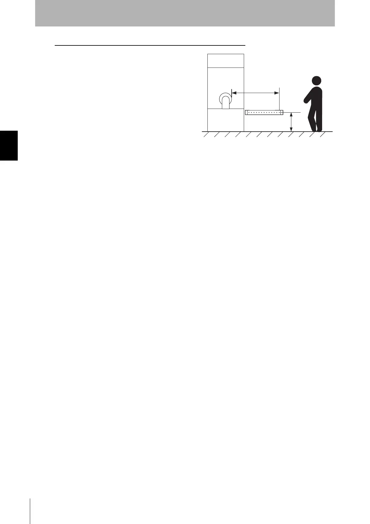
If a person approaches the detection zone of the F3SJ-B horizontally
Use K = 1,600 mm/s and C = (1200 - 0.4 x H) in
formula (1) for calculation.
Note that C must not be less than 850 mm.
S = 1,600 mm/s x (Tm + Ts) + 1200 - 0.4 x H
•S = Safety distance (mm)
•Tm = Machine's response time (s)
•Ts = Response time of the F3SJ-B from ON to
OFF (s)
•H = Installation height of the F3SJ-B (mm)
Note that H must satisfy:
1000 >= H >= 15 (d - 50 mm)
Also, you must include a hazardous condition under which a person may go carelessly through under
a detection zone if it exceeds 300 mm (200 mm for other purpose than industrial use) into risk
assessment.
[Calculation example]
When Tm = 0.05 s, Ts = 0.015 s, d = 25 mm, and H = 500 mm:
S = 1,600 mm/s x (0.05 s + 0.015 s) + 1200 - 0.4 x 500 mm
= 1,104 mm
How to calculate the safety distance specified by American Standard ANSI B11.19
(reference)
If a person approaches the detection zone of the F3SJ-B perpendicularly, calculate the safety distance
as shown below.
S = K x (Ts + Tc + Tr + Tbm) + Dpf
•S: Safety distance
•K: Approach speed to the detection zone (the value recommended by OSHA standard is 1,600 mm/s)
Approach speed K is not specified in the ANSI B.11.19 standard. To determine the value of K to apply,
consider all factors, including the operator's physical ability.
•Ts = Machine's stopping time (s)
•Ts = Response time of the F3SJ-B from ON to OFF (s)
•Tc = Machine control circuit's maximum response time required to activate its brake (s)
•Tbm = Additional time (s)
If a machine has a brake monitor, "Tbm = Brake monitor setting time - (Ts + Tc)". If it has no brake
monitor, we recommend using 20% or more of (Ts + Tc) as additional time.
•Dpf = Additional distance
According to ANSI's formula, Dpf is calculated as shown below:
Dpf = 3.4 x (d - 7.0): Where d is the detection capability of the F3SJ-B (unit: mm)
[Calculation example]
When K = 1,600 mm/s, Ts + Tc = 0.06 s, brake monitor setting time = 0.1 s,
Tr = 0.015 s, and d = 25 mm:
Tbm = 0.1 - 0.06 = 0.04 s
Dpf = 3.4 x (25 - 7) = 61.2 mm
S = 1,600 mm/s x (0.06 s + 0.015 s + 0.04 s) + 61.2 mm = 245.2 mm
Hazard
Safety distance (S)
H

 Loading...