27
F3SJ-B
User’s Manual
Chapter3 Series Connection
Wiring/Installation
E
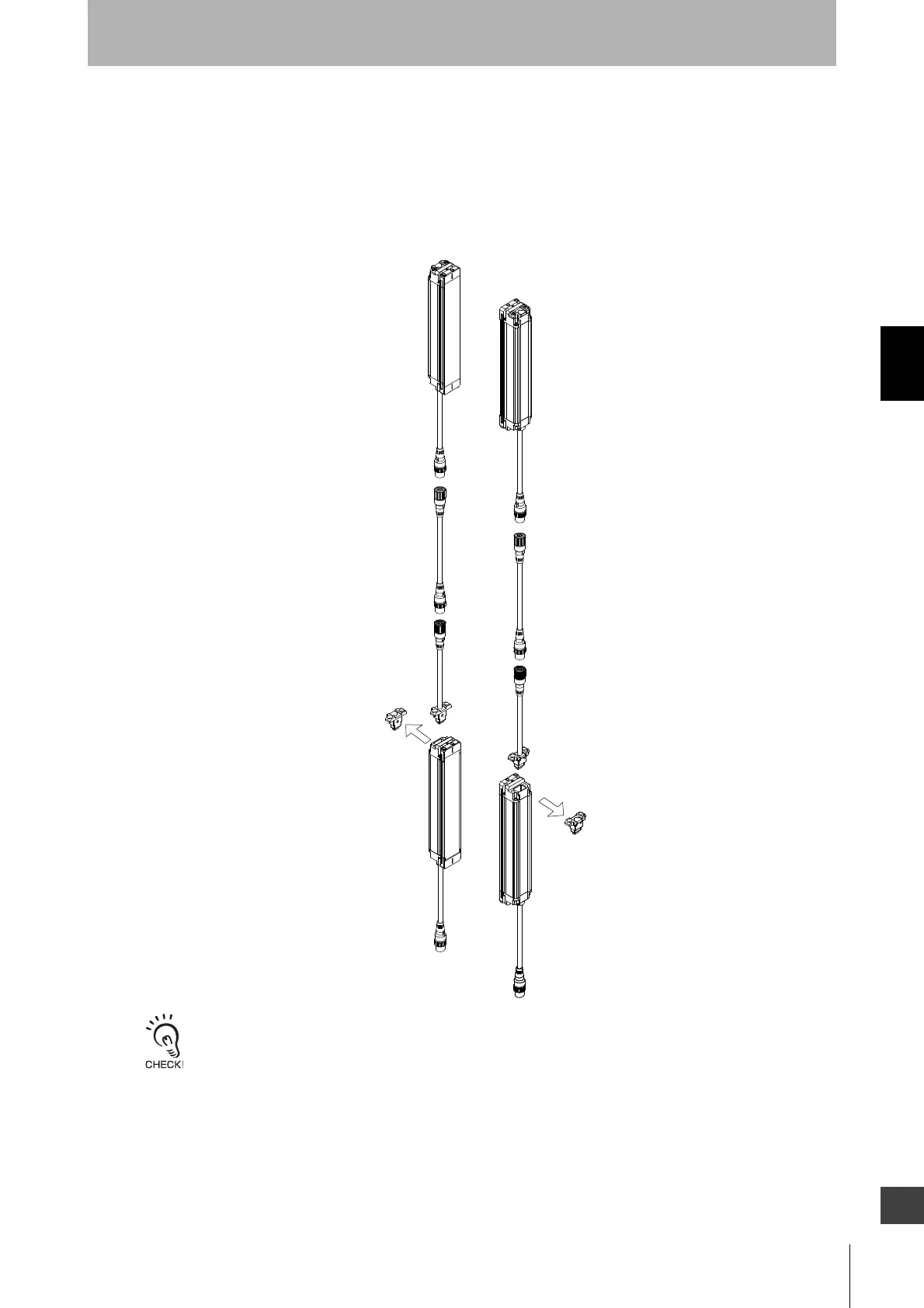
Connection Procedure
1. Remove the caps from the primary sensor. Loosen the screw (M3 cross-shaped) to remove the cap.
2. Use the F39-JBR2W series connection cable for extension to connect them.
3. When changing the connection distance between the F3SJ-Bs, connect a F39-JDB double-ended
connector cable (sold separately).
- When attaching a cable or cap, securely fasten the screws (M3 cross-shaped (2 for each), recommended torque:
0.54 N•m).
Failure to do so may cause the cable/cap to come loose, leading to deterioration of the protective functions.
- Attaching/detaching of a cap or a series-connection cable may cause misalignment of rubber grommet in a
connector assembly.
Press the grommet to the bottom of the connector and attach the connector F3SJ-B again.
1. 1.
1. 1.
2. 2.
2. 2.
3. 3.
3. 3.
Cap
Cap
F39-JBR2W
F39-JD
□B
F39-JBR2W
F39-JD
□B
Receiver’s
power supply
cable end
Emitter’s
power supply
cable end
Emitter’s
power supply
cable end
Receiver’s
power supply
cable end
<Secondary sensor>
<Primary sensor>

 Loading...