66
Chapter3 Wiring
F3SJ-B
User’s Manual
Wiring/Installation
Wiring Method
Perform wiring according to the following procedure.
1. Connect an emitter cable (F39-JD-L, gray, sold separately) to the emitter's connection cable (gray).
2. Connect a receiver cable (F39-JD-D, black, sold separately) to the receiver's connection cable
(black).
3. Connect the +24 V line of the power supply directly to the protective earth (PE).
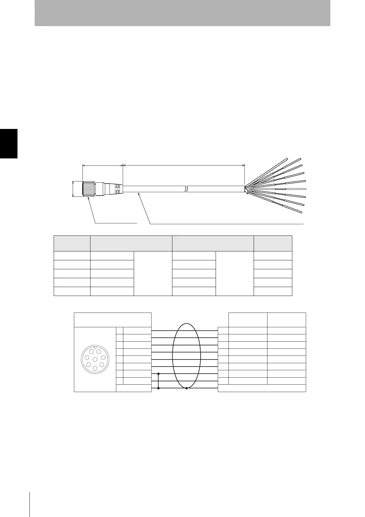
Single-ended connector cable (F39-JDA, sold separately)
<Internal wiring diagram> (F39-JDA-L, F39-JDA-D)
Set model
name
Emitter cable Receiver cable L (mm)
F39-JD3A F39-JD3A-L Gray cable F39-JD3A-D Black cable 3000
F39-JD7A F39-JD7A-L F39-JD7A-D 7000
F39-JD10A F39-JD10A-L F39-JD10A-D 10000
F39-JD15A F39-JD15A-L F39-JD15A-D 15000
F39-JD20A F39-JD20A-L F39-JD20A-D 20000
Insulated vinyl round cable dia. 6.6, shielded 8-wire (4-pair)
(Cross section of conductor: 0.3mm
2
/insulator diameter: dia. 1.15mm)
dia.15
39.5
L
M12 IP67 connector
(Unit: mm)
White
Brown
Black
Yellow
Gray
Pink
Blue
Red
1
2
3
4
5
6
7
8
NC
+24 VDC
Test input
Reset input
Communication line (+)
Communication line (-)
Communication line (+)
Communication line (-)
0V
NC NC
5
8
4
3
2
1
7
6
Connected to connection cable or
double-ended connector cable
Shield
Shield
Female
Safety output 2
+24 VDC
Safety output 1
Auxiliary output
0V
White
Brown
Black
Yellow
Gray
Pink
Blue
Red
Emitter Receiver
Twisted pair wires are white and red, brown and blue, black and yellow, and gray and pink

 Loading...