75
F3SJ-B
User’s Manual
Chapter4 Wiring Examples
Input/Output Circuit and Applications
E
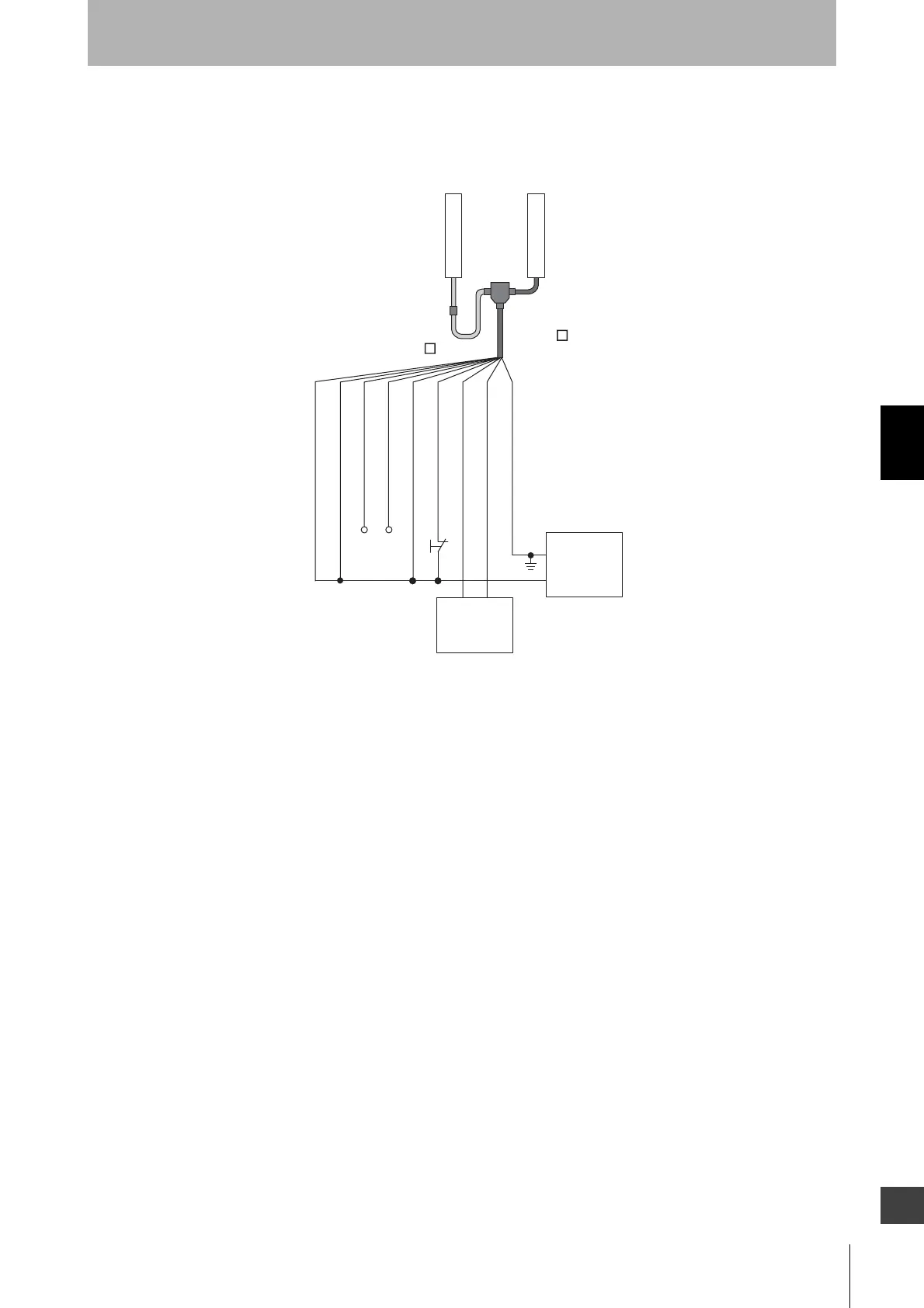
Using a simple wiring connector for F3SJ-B
•A combination of a cable for simple wiring (F39-JDBA) and a simple wiring connector (F39-CN5)
can be used for a simple wiring system.
Note1:When using the Simple Wiring Connector (F39-CN5), the following functions are not available.
• Auxiliary Output
Note2:F39-JDB-L is connected to the emitter by the above picture, but even if F39-JDB-L is
connected to the receiver, F3SJ operates.
F39-JD A-D
F39-CN5
Receiver
Emitter
F39-JD B-L
+24V DC
0V
Power
supply
Safety
controllers,
etc.
0V (Blue)
Shield
+24V (Brown)
Test input (Red)
Reset input (Yellow)*2
Safety output 1 (Black)
Safety output 2 (White)
Communication line (+) (Grey)*3
Communication line (-) (Pink)*3
S1 : External test switch (connect 0 V if a switch is
not required)
*1. Use a switch for small loads (input specificatio
24 V, 1.0 mA max.).
*2. When the lockout reset function is used, conne
to 0 V via a lockout reset switch (N.C. contact)
*3. Make sure the Communication lines are
insulated. If the lines are shorted, the F3SJ-B
enters the lockout state.
S1
*1

 Loading...