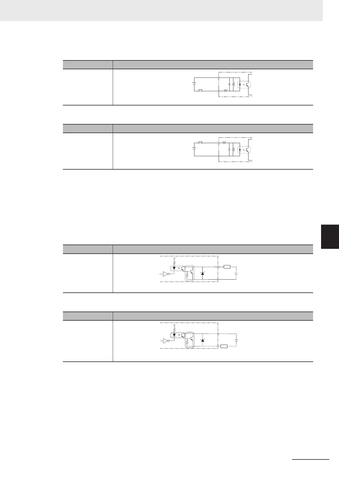
a) Internal specifications for NPN connection
Item Specifications
Internal circuit dia-
gram
COM IN
+
Each input terminal
b) Internal specifications for PNP connection
Item Specifications
Internal circuit dia-
gram
COM IN
+
Each input terminal
[Output]
Object signals:
•
No.15 to 19 pin, No.28 to 32pin: Use the COMOUT0 terminal when using these signals.
• No.48 to 57 pins: Use the COMOUT2 terminal when using these signals.
• No.58 to 66 pins: Use the COMOUT3 terminal when using these signals.
a) Internal specifications for NPN connection
Item Specifications
Internal circuit dia-
gram
Each output terminal
Load
COM OUT
+
b) Internal specifications for PNP connection
Item Specifications
Internal circuit dia-
gram
COM OUT
+
Each output terminal
Load
[Output]
Object signals:
•
No.20 to 27 pins: Connect the COMOUT1 and COMIN0 terminals when using these signals.
a) Internal specifications for NPN connection
6 I/O Interface
6-9
FH Series Vision System Hardware Setup Manual for 3D Robot Vision (Z436-E1)
6-1 Parallel Interface
6
6-1-1 FH-5050

 Loading...


