COMIN0 to 2: Common for input signals, COMOUT0 to 3: Common for output signals,
DI0 to 7: Command inputs, DILINE0 to 2: Command inputs (Line specified) ,
ENCTRIG_A0 to 1: Encoder trigger input for phase A, ENCTRIG_B0 to 1: Encoder trigger input for phase B,
ENCTRIG_Z0 to 1: Encoder trigger input for phase Z, STEP0 to 7: Measurement trigger
,
ACK: Instruction execution complete flag, BUSY0 to 7: ON during processing,
DO0 to 15: Data outputs, ERROR: ON when an error occurs
*5
,
ERROR0 to 3: ON when an error occurs, GATE0 to 1: ON during set output time,
OR0 to 7: Overall judgment results, READY0 to 7: ON when image input is permitted,
RUN0 to 3: ON when switched to output specified layout,
SHTOUT0 to 7: Shutter output signals, STGOUT0 to 7: Strobe trigger signals
*4
*1. Use the STEP signal when using measurement trigger inputs. Use the ENCTRIG_A0/B0/Z0 when using en-
coder inputs
*2. When using one measurement trigger and one encoder input in the 2-line random mode, use
ENCTRIG_A0/B0/Z0 and STEP1.
*3. Do not connect anything for "Not used".
*4. This signal is used when the strobe signal is used for the Sensor Controller.
*5. The ERROR signal is shared among No.1 to 8 line.
Internal Specifications for Parallel Interface
The parallel interface can be used for both NPN and PNP. Connect the pins properly according to the
specifications of external devices.
[Input]
Object signals:
•
No.14 pin: Use the COMIN1 terminal when using these signals.
• No.37 to 46 pins: Use the COMIN2 terminal when using these signals.
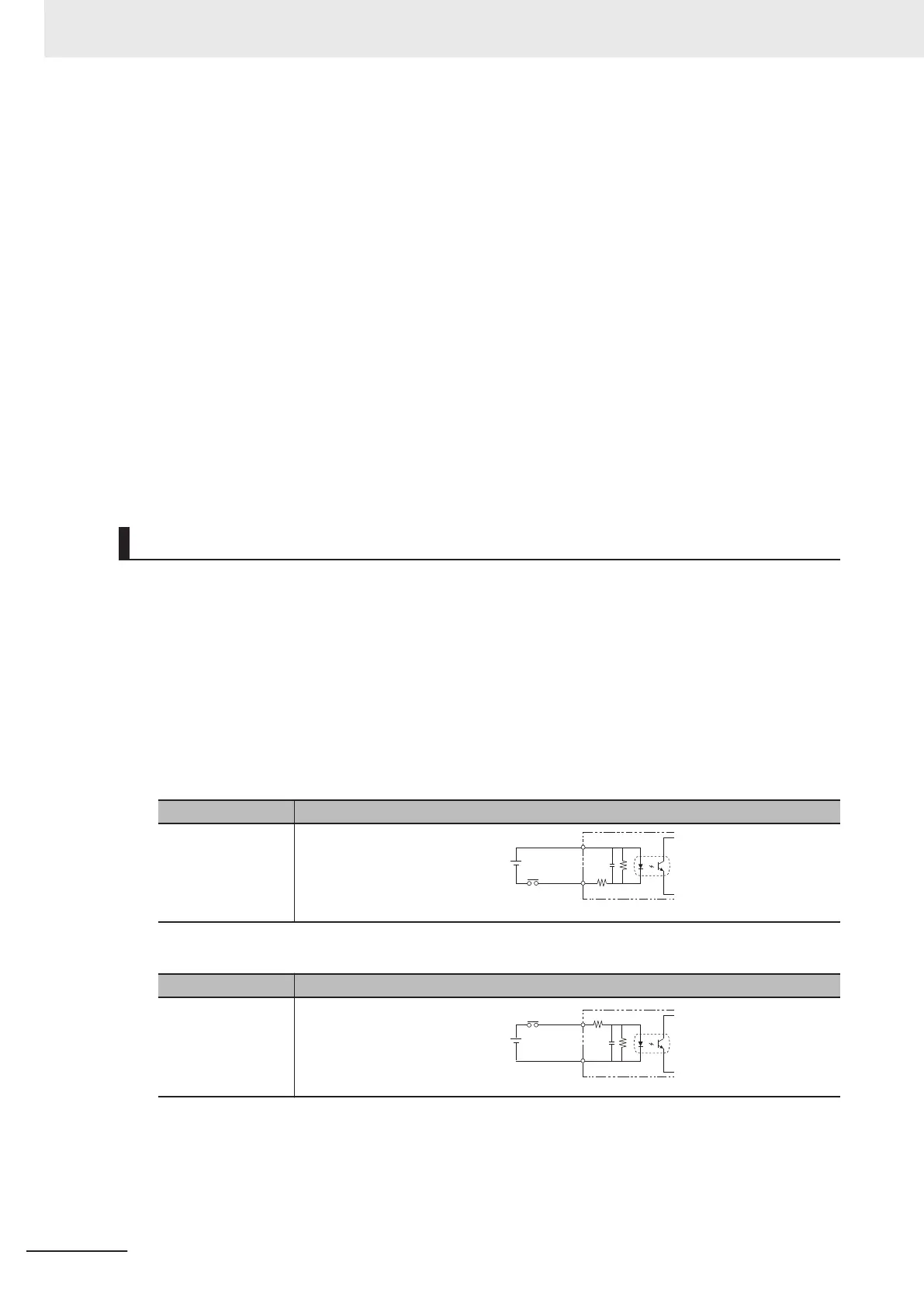
a) Internal specifications for NPN connection
Item Specifications
Internal circuit dia-
gram
COM IN
+
Each input terminal
b) Internal specifications for PNP connection
Item Specifications
Internal circuit dia-
gram
COM IN
+
Each input terminal
[Input]
Object signals:
•
No.4 to 6, 9 to 11 pins: Use the COMIN1 terminal when using these signals.
• No.7, 8, 12, 13 pins: Use the COMIN0 terminal when using these signals.
6 I/O Interface
6-8
FH Series Vision System Hardware Setup Manual for 3D Robot Vision (Z436-E1)

 Loading...


