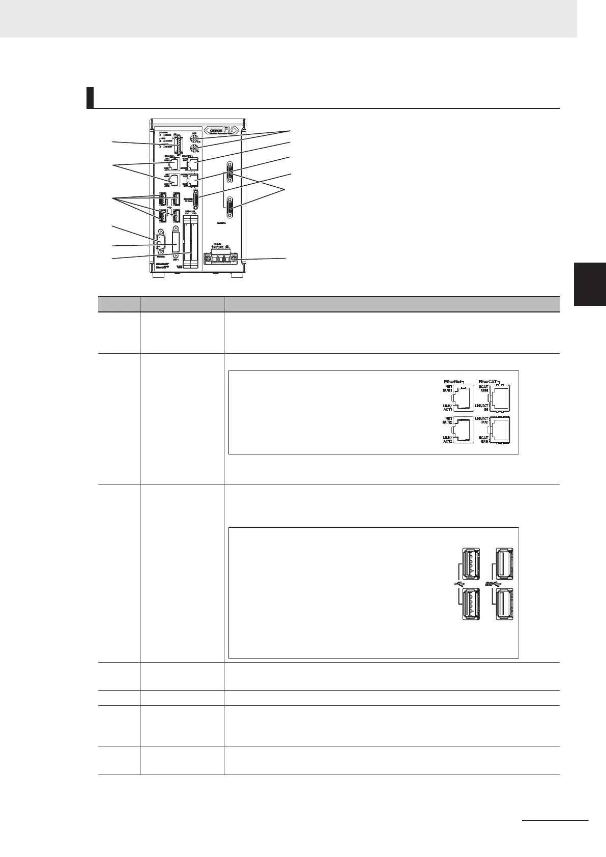
Component Names and Functions
(A)
(B)
(C)
(D)
(E)
(F)
(G)
(H)
(I)
(K)
(L)
(J)
Connector name Description
(A) SD memory card
installation con-
nector
Install the SD memory card. Do not plug or unplug the SD memory card during
measurement operation. Otherwise measurement time may be af
fected or data
may be destroyed.
(B) Ethernet connec-
tor
Connect an Ethernet device.
Upper port :
Ethernet port
Lower port :
Ethernet port, EtherNet/IP port, and PROFINET port
are sharing use.
Connect the camera cable (Ethernet cable FHV-VN£BX: sold separately) to the
upper port.
(C) USB connector Connect a USB device.
Do not plug or unplug it during measurement. Otherwise measurement time may
be af
fected or data may be destroyed.
Left ports: USB2.0
Right ports: USB3.0
The USB3.0 interface has a higher bus power supply
capability than the USB2.0 interface, and you can expect
more stable operation with it.
Also, when used in combination with a USB3.0 device, you
can expect higher transfer speed than USB2.0.
Be sure to give priority to using the USB3.0 interface.
(D) RS-232C connec-
tor
Connect an external device such as a touch panel monitor.
(E) DVI-I connector Connect a monitor.
(F) I/O (Parallel) con-
nector (control
lines, data lines)
Connect the controller to external devices such as a sync sensor and PLC.
(G) EtherCAT address
setup volume
Used to set a station address (00 to 99) as an EtherCAT communication device.
3 Configuration
3-5
FH Series Vision System Hardware Setup Manual for 3D Robot Vision (Z436-E1)
3-1 Sensor Controller
3
3-1-1 FH-5050

 Loading...


