Connector name Description
(H) EtherCAT commu-
nication connector
(IN)
Connect the opposed EtherCAT device.
(I) EtherCAT commu-
nication connector
(OUT)
Connect the opposed EtherCAT device.
(J) Encoder connec-
tor
Not supported.
(K) Camera connec-
tor
Not supported.
Do not connect cameras.
(L) Power supply ter-
minal connector
Connect a DC power supply. Wire the FH Sensor Controller independently on
other devices.
Wire the ground line. Be sure to ground the FH Sensor Controller alone.
Use an attachment power terminal (male) for installation. For details, refer to
5-3 Sensor Controller Installation on page 5-
5.
(A)
(B)
(C)
(D)
(E)
(F)
(G)
(H)
(I)
(J)
(K)
(L)
(M)
(N)
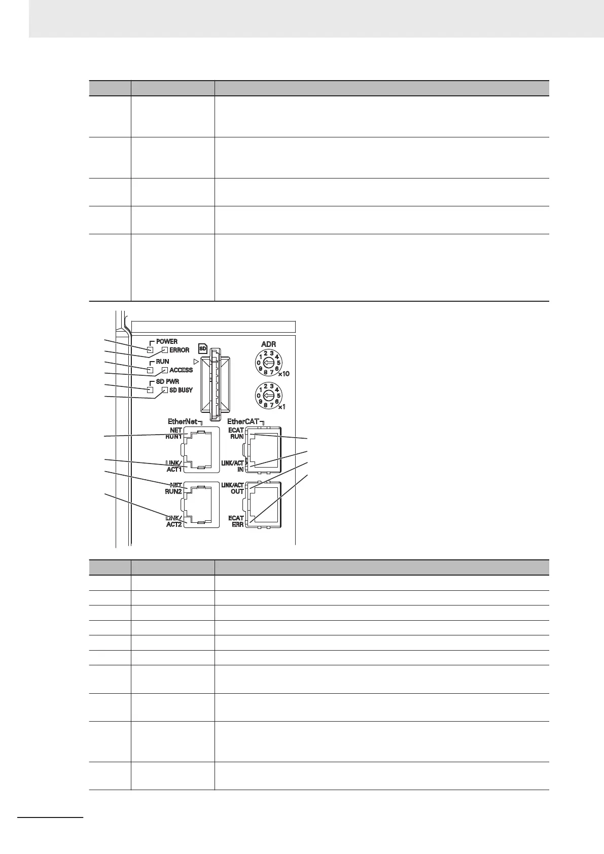
LED name Description
(A) POWER LED Lit while power is ON.
(B) ERROR LED Lit when an error has occurred.
(C) RUN LED Lit while the layout turned on output setting is displayed.
(D) ACCESS LED Blinks while the internal nonvolatile memory is accessed.
(E) SD POWER LED Lit while power is supplied to the SD memory card and the card is usable.
(F) SD BUSY LED Blinks while the SD memory card is accessed.
(G) EtherCAT RUN
LED
Lit while EtherCAT communications are usable.
(H) EtherCAT
LINK/ACT IN LED
Lit when connected with an EtherCAT device, and blinks while performing com-
munications.
(I) EtherCAT
LINK/ACT OUT
LED
Lit when connected with an EtherCAT device, and blinks while performing com-
munications.
(J) EtherCAT ERR
LED
Lit when EtherCAT communications have become abnormal.
3 Configuration
3-6
FH Series Vision System Hardware Setup Manual for 3D Robot Vision (Z436-E1)

 Loading...


