Component Names and Functions
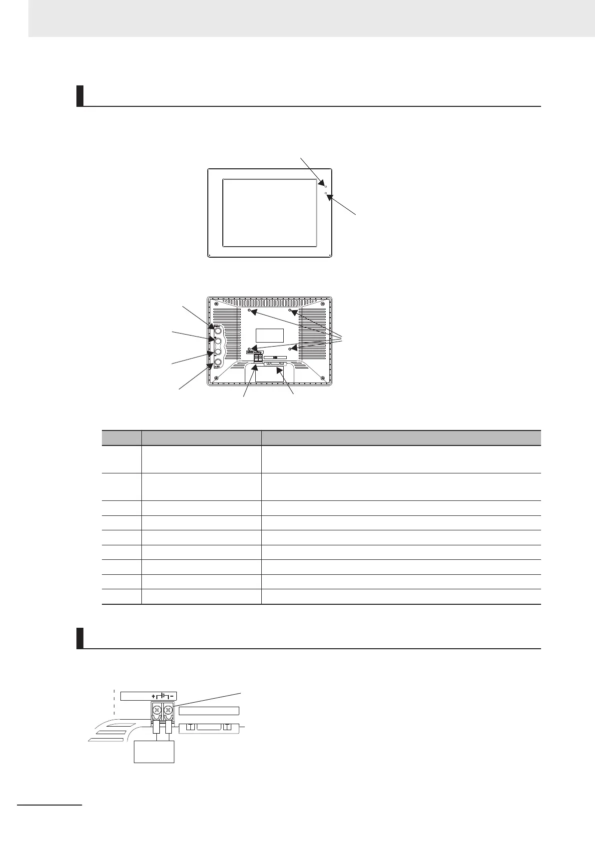
Front View
Display section
(1) LED indicator lamp (for power)
(2) LED indicator lamp
(for SYNC)
Rear
(5) MENU button
(6) + button
(7) - button
(4) Video input (RGB)
(3) Power connection
terminal
(8) AUTO button
(9) VESA mounting
hole (M4)
Name Description
(1) LED indicator lamp (for
power)
Lit up green when power is ON.
(2) LED indicator lamp (for
SYNC)
Lit up orange while the video signal is input.
(3) Power supply terminal Connect a 24 VDC power supply.
(4) Video input (RGB) Video input terminal (RGB)
(5) MENU button OSD operating button (MENU button)
(6) + button OSD operating button (+ button)
(7) - button OSD operating button (- button)
(8) AUTO button OSD operating button (AUTO button)
(9) VESA mounting hole (M4) Mounting hole for VESA 75 mm x 75 mm.
Wire
The power terminal block for the Touch Panel Monitor is located on the back of it.
Connect a power supply of 24 VDC there.
M3
(Outside diameter of crimp terminal:
Dia 5.5 mm maximum)
Recommended model
OMRON Corporation-manufactured
S8VS-03024
24 VDC
RGB
Power
supply
24 VDC
• Keep the power supply wires as short as possible (maximum 10 m).
3 Configuration
3-26
FH Series Vision System Hardware Setup Manual for 3D Robot Vision (Z436-E1)

 Loading...


