• If UL recognition is required, use a UL class II power supply.
Regarding installation, do not use the VESA mounting but fix the monitor unit using the board mount-
ing.
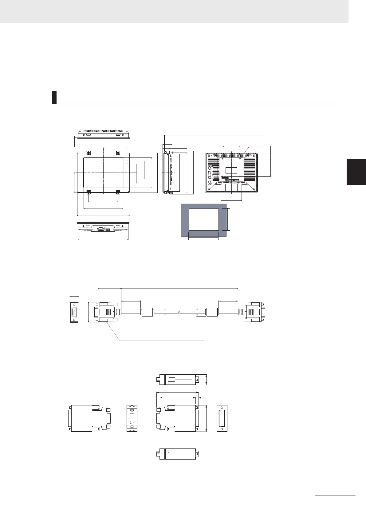
Dimensions
LCD Monitor
(Unit: mm)
221.5
+0.5
-0mm
Panel cut drawing
161.5
+0.5
-0mm
(103.5)
(130)
(172)
230
(85.5)
(38)
(12.5)
(129.4)
171
(90)
75
4-M4
75
26
(31.5)
40
Mountable board thickness: 1.6 to 4.8
(173.4)
(185)
161
220
(6)
Monitor Cable: FZ-VM
(15)
Two, 15-pin rectangular connector
(32.5)
4.5 dia.
(14 dia.)
(33.5)
(32.5)
(39)
L(*1)
(Unit: mm)
*1. Cable is available in 2 m/5 m.
DVI-I -RGB Conversion Connector: FH-VMRGB
63.8
15.740
54 4.9
(Unit: mm)
3 Configuration
3-27
FH Series Vision System Hardware Setup Manual for 3D Robot Vision (Z436-E1)
3-5 LCD and Cable
3

 Loading...


