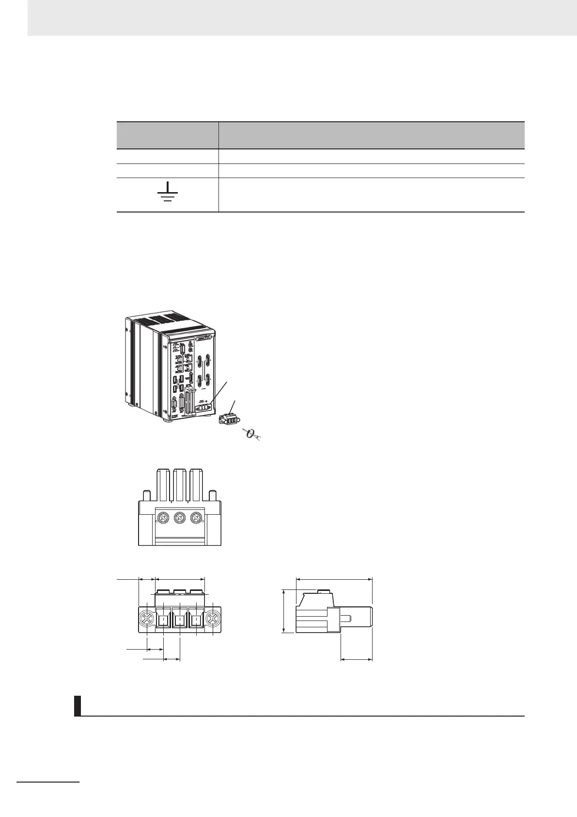
2 Connect the wire and power source to the terminal block connector (male) depending on the
indicated terminal block connector
.
Indicate of terminal
block connector
Function
+ Connect the DC output positive (+V) of 24 VDC power.
- Connect the DC output positive (-V) of 24 VDC power.
Connect the earth.
3 Insert the terminal block connector (male) to the terminal block connector (female) of Sensor
Controller
.
4 Tightens and fix the left and right screws for the terminal block connector (male). (Recommend-
ed tightening torque: 0.7 to 0.8 N•m)
Terminal block connector (female)
Terminal block connector (male)
14.7
7.64 22.81
19.7
35.3
7.62
7.62
(Unit: mm)
Recommended Power Source of Sensor Controller
Power source types for FH series differ depending on the number of cameras due to current consump-
tion dif
ferences. Refer to the following table to use the appropriate type.
5 Setup and Wiring
5-6
FH Series Vision System Hardware Setup Manual for 3D Robot Vision (Z436-E1)

 Loading...


