When you connect your camera to the lighting via Light Controller, the current consumption is same as
when the Intelligent Compact Digital camera is connected.
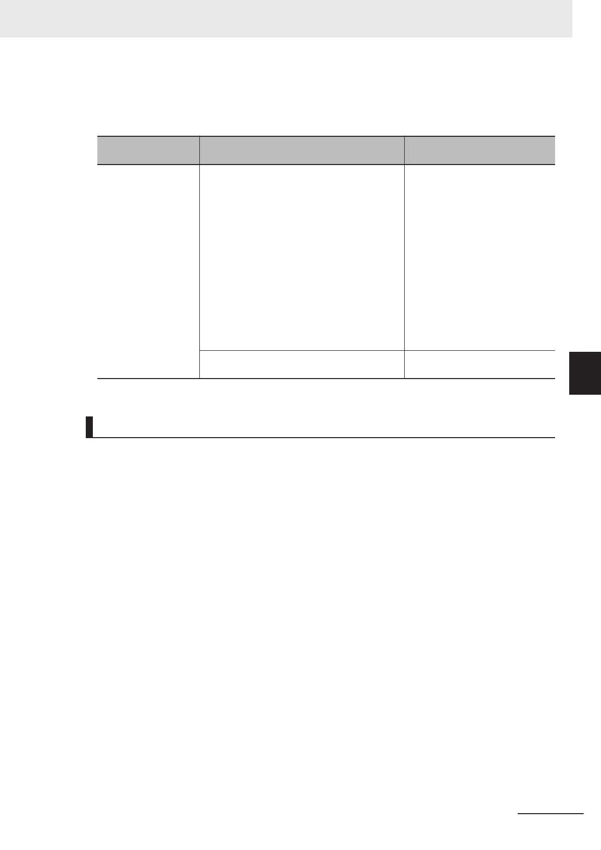
Item
Connected camera, Lighting controller, and
Lighting type
FH-5050
Recommended Power
Source
S8VK-G
S8VS
• When connecting intelligent compact digital
cameras:
• When connecting the following lightings or
light controllers without external power sup-
plies:
• FL
V-TCC1
• FLV-TCC4
• FLV-TCC3HB
• FLV-TCC1EP
• FL-TCC1
• When connecting the following lighting or light
controllers:
• FL-TCC1PS
• FL-MD£MC
S8VK-G24024
S8VS-18024
Other than above case S8VK-G12024
S8VS-12024
Mounting of Sensor Controller
• Make sure to tighten all screws in mounting.
•
For good ventilation, provide a clearance of 50 [mm] or more above the Sensor Controller away
from other devices in the normal floor mounting. For the right and left sides, provide a clearance of
30 [mm] or more, and for the back side, 15 [mm] or more. These clearances are also required when
mounting multiple Sensor Controllers side by side. For the back mounting, the back-side clearance
of 15 [mm] is not required.
• Do not install the product immediately above significant heat sources, such as heaters, transform-
ers, or large-capacity resistors.
• Do not install the Sensor Controller in a cabinet with high-voltage equipment installed.
• Mount the Sensor Controller at 200 [mm] or more from power cables apart.
5 Setup and Wiring
5-7
FH Series Vision System Hardware Setup Manual for 3D Robot Vision (Z436-E1)
5-3 Sensor Controller Installation
5
5-3-1 FH-5050

 Loading...


