18
2-3-2 Relay Output Board
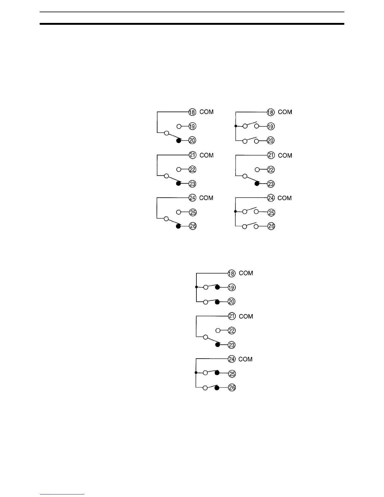
The following figures show the connections for relay output.
K3NR with 3 Relay
Output Boards,
K31-C1
K3NR with 5 Relay
Output Boards,
K31-C2
H
comparative
output
HH comparative
output
H comparative
output
PASS
output
PASS
output
L
comparative
output
L comparative
output
LL comparative
output
HH comparative
output
PASS
output
LL comparative
output
H comparative
output
L comparative
output
K3NR with 5 Relay
Output Boards,
K31-C5
The following contact output conditions are required.
5 A (resistive load) at 250 VAC
1.5 A (inductive load) at 250 VAC
5 A (resistive load) at 30 VDC
1.5 A (inductive load) at 30 VDC
Output Board
Section 2-3