7
1-3 Rear of the Meter
Terminal arrangement varies depending on the selected Output Board.
For wiring, refer to Section 2 Setup.
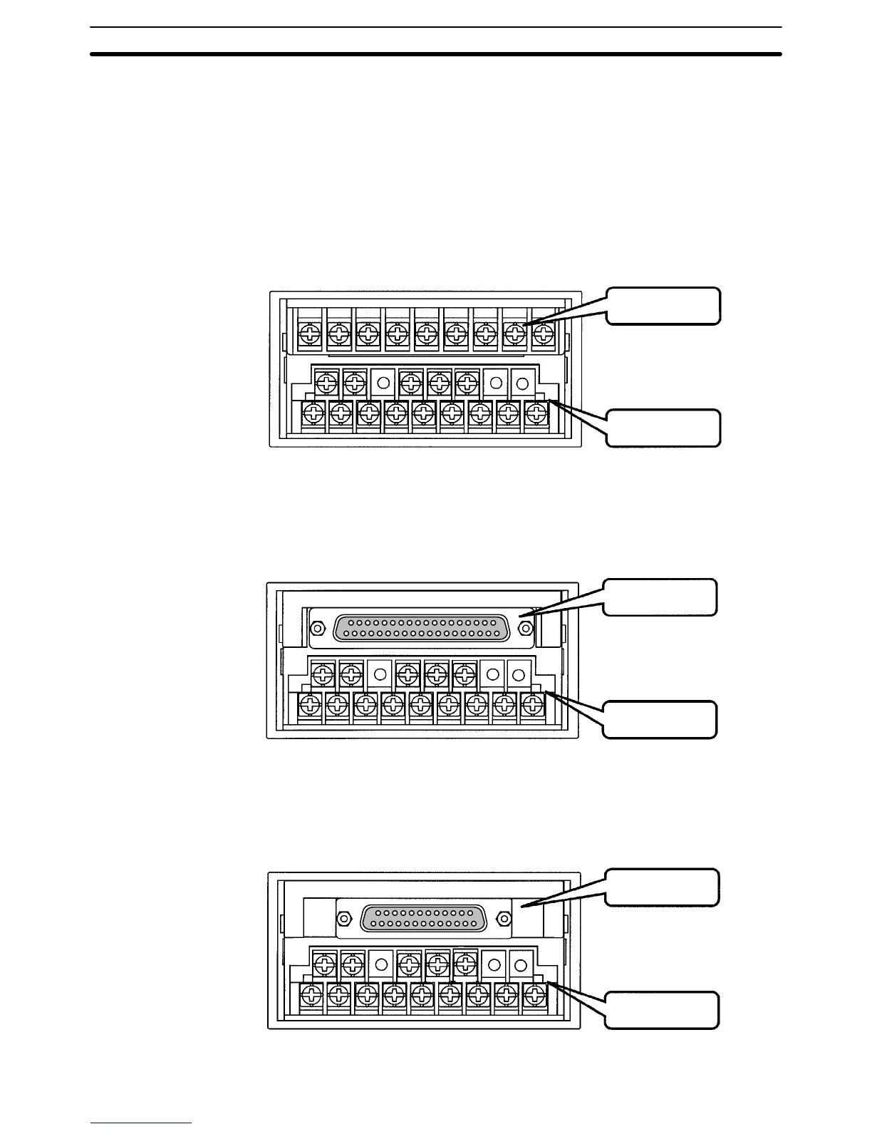
K3NR with Relay Output Board, K31-C1, -C2, -C5
K3NR with Transistor Output Board, K31-T1, -T2
K3NR with Linear Output Board, K31-L1, -L2, -L3, -L4, -L5, -L6, -L7, -L8, -L9, -L10
K3NR with RS-485 Output Board, K31-FLK2, -FLK5
Output Board
Input Board
K3NR with BCD Output Board, K31-B2, -B4
Output Board
Input Board
K3NR with RS-232C Output Board, K31-FLK1
Communications
Output Board
Input Board
Rear of the Meter
Section 1-3