Chapter 6: Connectivity
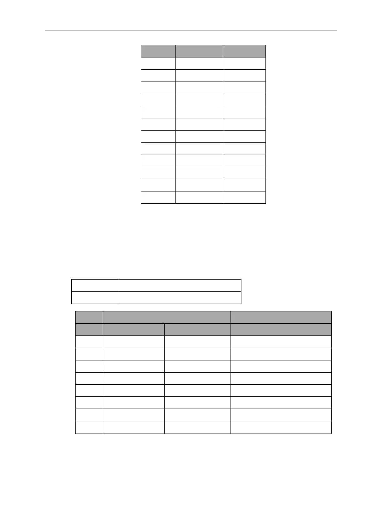
Pin No. Designation Notes
2 ANALOG_IN2 0-10 V Range
3 ANALOG_IN3 0-10 V Range
4 ANALOG_IN4 0-10 V Range
5 ANALOG_IN5 0-30 V Range
6 ANALOG_IN6 0-30 V Range
7 ANALOG_IN7 0-30 V Range
8 ANALOG_IN8 0-30 V Range
9 ANALOG_OUT1 0-20 V Range
10 ANALOG_OUT2 0-20 V Range
11 ANALOG_OUT3 0-20 V Range
12 ANALOG_OUT4 0-20 V Range
13, 14, 15 GND
l
The 0-10 V analog inputs have an input impedance of about 35 kΩ.
l
The 0-30 V analog inputs have an input impedance of about 110 kΩ.
l
The analog outputs have an output impedance of about 200 Ω.
The maximum output current of each analog output is 10 mA. Exceeding the maximum
output current will result in damage to the analog output module.
Aux Sensors
Connector type HDB15M
Use Side (vertical) and low sensing (foot)lasers
Designation
Pin No. Hardware Software Notes
1 RS232_VERT1_TXD /dev/ttyUSB5
2 RS232_VERT2_TXD /dev/ttyUSB6
3 RS232_FOOT_TXD /dev/ttyUSB7
4 5V_SW1 USB_1_and_2_Power 5 V @ 1 A (shared with USB port 1)
5, 10 SW_20V_VERT Vertical_Laser_Power 20 V @ 300 mA
6, 7, 8 GND
9 5V_SW2 USB_1_and_2_Power 5 V @ 1 A (shared with USB port 2)
11 RS232_VERT1_RXD /dev/ttyUSB5
14766-000 Rev H LD Cart Transporter User's Manual 95