Chapter 6: Connectivity
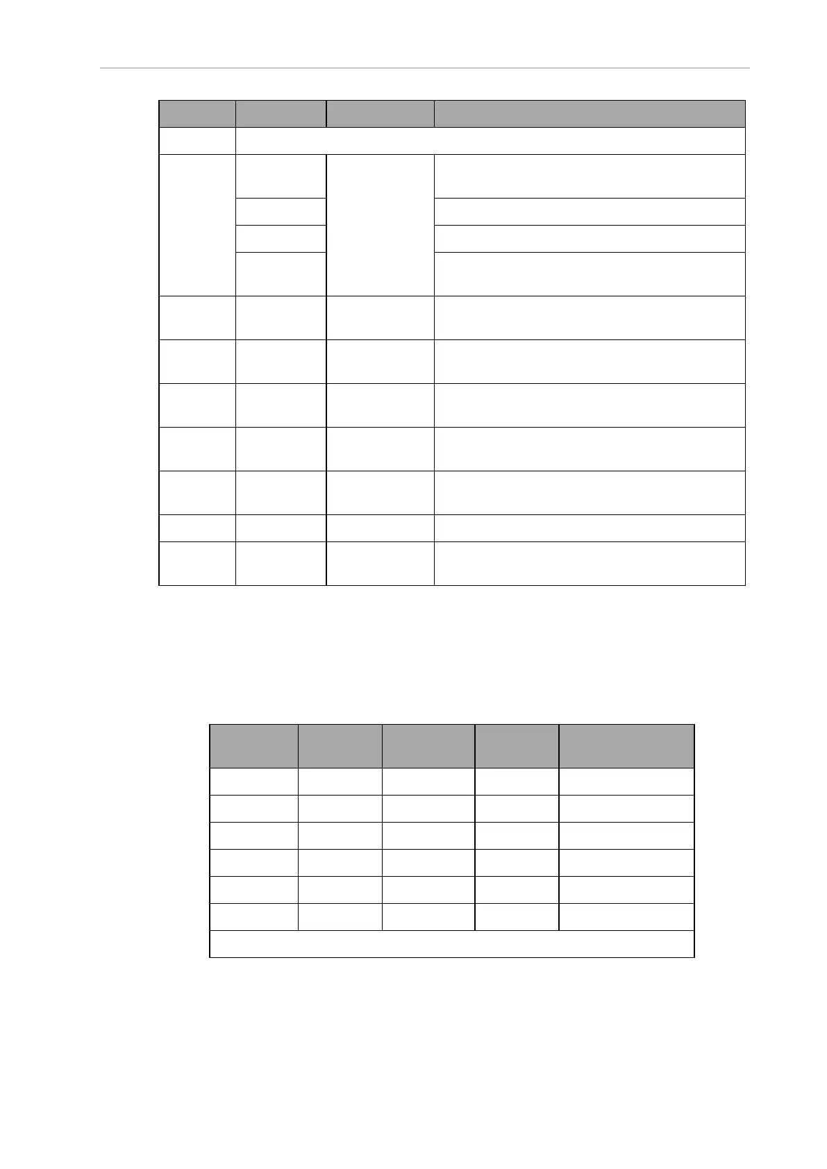
Callout Connection Type Description
NOTE:The following four functions are pins on the User Interface connector.
B Brake-
release
Mini-Fit 2 x 7 Pins for user-supplied brake release
ON Pins for user-supplied ON button
OFF Pins for user-supplied OFF button
ESTOP Pins for user-supplied E-Stop (must be used or
jumpered)
C User
Bumpers
Mini-Fit
2 x 4
This connection is not used with an LD Platform
Cart Transporter.
D Aux Power Mini-Fit
2 x 3
5, 12, and 20 VDC Outputs
E User Power Mini-Fit
2 x 6
Battery and switched battery power
J Maint LAN RJ45,
Shielded
Directly connected to the externally-mounted
Maintenance Ethernet, Auto-MDIX.
H Joystick DB9F Directly connected to the externally-mounted
Joystick port
G HMI Panel HDB15F Operator screen, E-Stop, Brake_Rel, ON, OFF
F Sonar 2 DB9M This connection is not used with an LD Platform
Cart Transporter.
Power Connections
The platform provides conditioned 5, 12, and 20 VDC, and raw (battery) 22 - 30 VDC power to
the platform’s and accessory electronics, including the onboard LD Platform core and safety
scanning laser LIDAR (Light Detection And Ranging).
All power connectors are Mini-Fit
®
.
Nominal Qty Actual
Maximum
Current
Description
5 VDC 1 5±5% VDC 1 A Switched Aux power
12 VDC 1 12±5% VDC 1 A Switched Aux power
20 VDC 1 20±5% VDC 1 A Switched Aux power
22 – 30 VDC 2 battery 4 A Switched
22 – 30 VDC 1* battery 10 A Switched
22 – 30 VDC 1* battery 10 A Safe, Switched
* 10 A Switched and 10 ASafe, Switched share the 10 A of current.
14766-000 Rev H LD Cart Transporter User's Manual 97