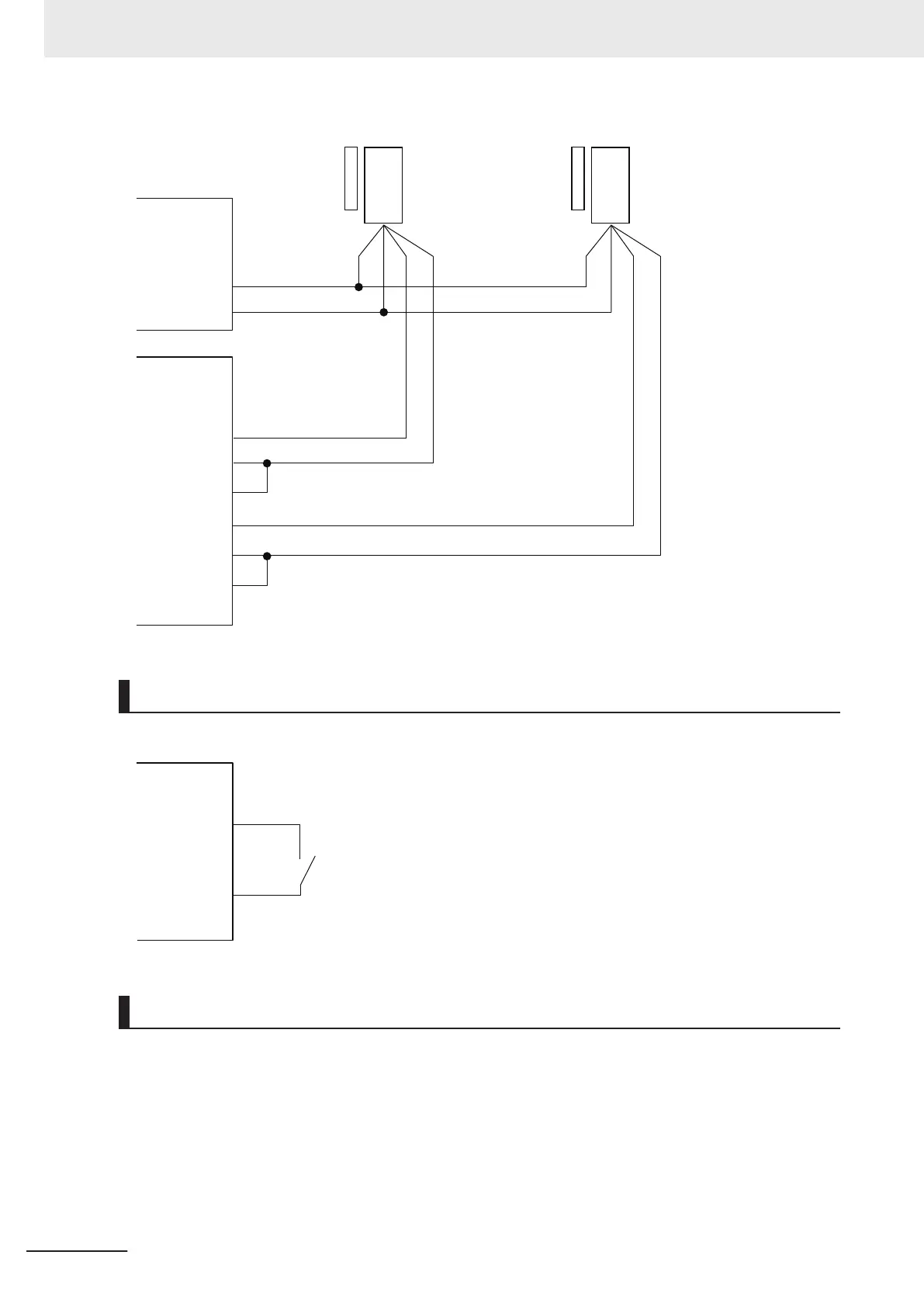
EasyManuals Logo

Omron NJ Series Startup Guide

Omron NJ Series
168 pages
To Next Page IconTo Next Page
To Previous Page IconTo Previous Page
Page #154 background imageLoading...
Page #154 background image
NX-SIH400
(N4)
I/O power
supply
Non-contact door switch Non-contact door switch
Non-contact door switch input
Non-contact door switch output
Non-contact door switch input
Non-contact door switch output
Si3
Si2
Si1
Si0
T0
T1
0V
24 VDC
Brown
Blue
Black
White
Brown
Blue
Black
White
Wiring the Reset Switch
Connect the reset switch to the Safety Input Unit (N5).
NX-SIH400
(N5)
Si0
T0
Wiring the Robot
Connect the robot to the Safety Output Unit (N6), Safety Input Unit (N5) and safety relays.
The outputs of the Safety Output Unit (N6) and the inputs of the robot cannot be directly connected,
therefore they are connected through the safety relays.
Use the contact a of each safety relay L1 to L4.
Appendices
A-10
NJ-series Robot Integrated System Startup Guide (O049)

Table of Contents

Other manuals for Omron NJ Series

Questions and Answers:

Question and Answer IconNeed help?

Do you have a question about the Omron NJ Series and is the answer not in the manual?

Omron NJ Series Specifications

General IconGeneral
Program CapacityUp to 128 MB
SD Card SlotYes
Power Supply Voltage24 VDC
Motion ControlYes
USB Ports1
Operating Temperature0°C to 55°C
Communication InterfacesEthernet/IP, EtherCAT, USB
Safety FunctionOptional
Storage Temperature-20°C to 75°C
Communication PortsUSB
DimensionsVaries by model
WeightVaries by model

Related product manuals