A-1 Comparison between NS-series PTs and CX-Programmer
A-1-1 Ladder Program Display
100
A-1 Comparison between NS-series PTs
and CX-Programmer
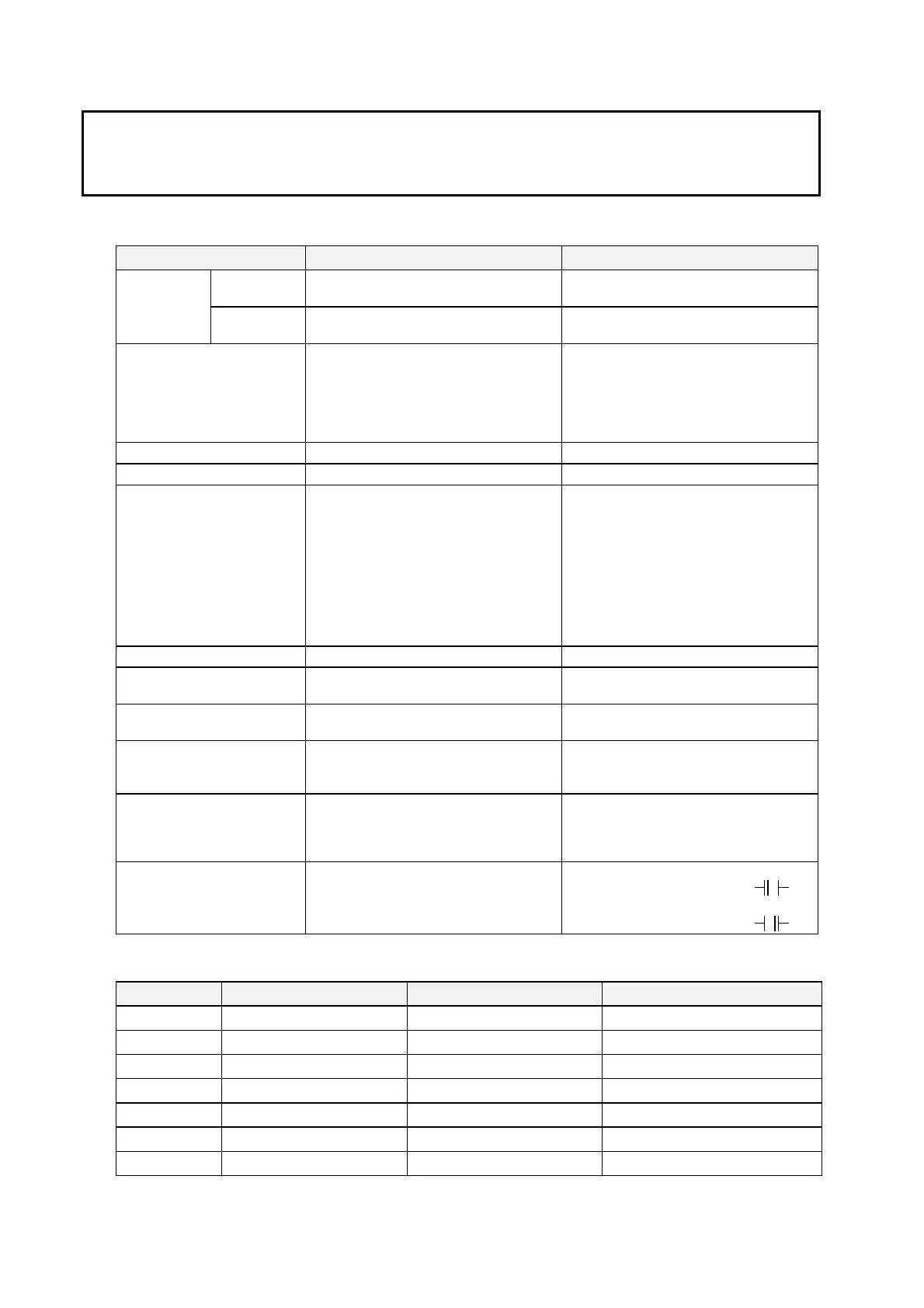
A-1-1 Ladder Program Display
Function NS Series CX-Programmer
No. of rows 22 rows. Overflowed rows will cause a
program section error.
No limitation Limitation for
one program
section
No. of TR bits
Displays program sections with 8 TR bit
max. Cannot display 9 or more TR bits.
The program section with up to 16 TR bits
can be displayed as ladder diagram.
Continuity display A program section with more than the
maximum number of input bits (21 for the
NS15, 16 for the NS12, or 13 for the
NS10/8) connected by AND is displayed
and lines are wrapped using the
continuation symbol (-■).
Connected in a series by input bit AND.
No limitation
No wrapping
Checked by horizontal scroll
Special instruction display Horizontal display on one step Vertical display on multiple steps
Mnemonic display None Possible
I/O Comments display On the ladder program section: Up to 5
characters
I/O comments can be displayed in 1 or 3
lines.
Detail: Up to 71 characters for the NS15,
up to 43 characters for the NS12, or up to
23 characters for the NS10/8
Total number of I/O comments:
Global comments: 65,535
Local comments: 65,535
•
Up to 255 characters. 10 lines can be
displayed.
Total number of I/O comments:
Global comment: No limitation
Local comment: No limitation
I/O name (variable) display None Ladder with variables can be displayed.
Displaying rung annotation,
rung comment, comment box
None Possible
Displaying bits in the Auxiliary
Area
Displayed by address (e.g., A200.11).
Refer to the following table.
The name is displayed.
(e.g., P_First_Cycle)
Displaying input bits with
differentiation and Immediate
refreshing
Displayed by
↑
,
↓
, and !.
Displayed by
↑
,
↓
, and !.
Displaying differentiation of
special instruction
Displaying immediate
refreshing
Displayed @ for differentiation up, % for
differentiation down, and ! for immediate
refresh
Displayed @ for differentiation up, % for
differentiation down, and ! for immediate
refresh
Displaying operand bits for
DIFU and DIFD instructions
Normal input bit display when a DIFU or
DIFD operand is an input bit.
When a DIFU operand is an input bit, the
input bit symbol is displayed as
.
When a DIFD operand is an input bit, the
input bit symbol is displayed as
.
The following bits in the Auxiliary Area are displayed differently by the Ladder Monitor and the
CX-Programmer.
Address Display on Ladder Monitor Display on CX-Programmer I/O comment
A200.11 A200.11 P_First_Cycle First Cycle Flag
A200.12 A200.12 P_Step Step Flag
A200.15 A200.15 P_First_Cycle_Task Initial Task Execution Flag
A401.08 A401.08 P_Cycle_Time_Error Cycle Time Too Long Flag
A402.04 A402.04 P_Low_Battery Battery Error Flag
A402.09 A402.09 P_IO_Verify_Error I/O Verification Error Flag
A500.15 A500.15 P_Output_Off_Bit Output OFF Bit

 Loading...


