1-5 System Configuration
27
1-5 System Configuration
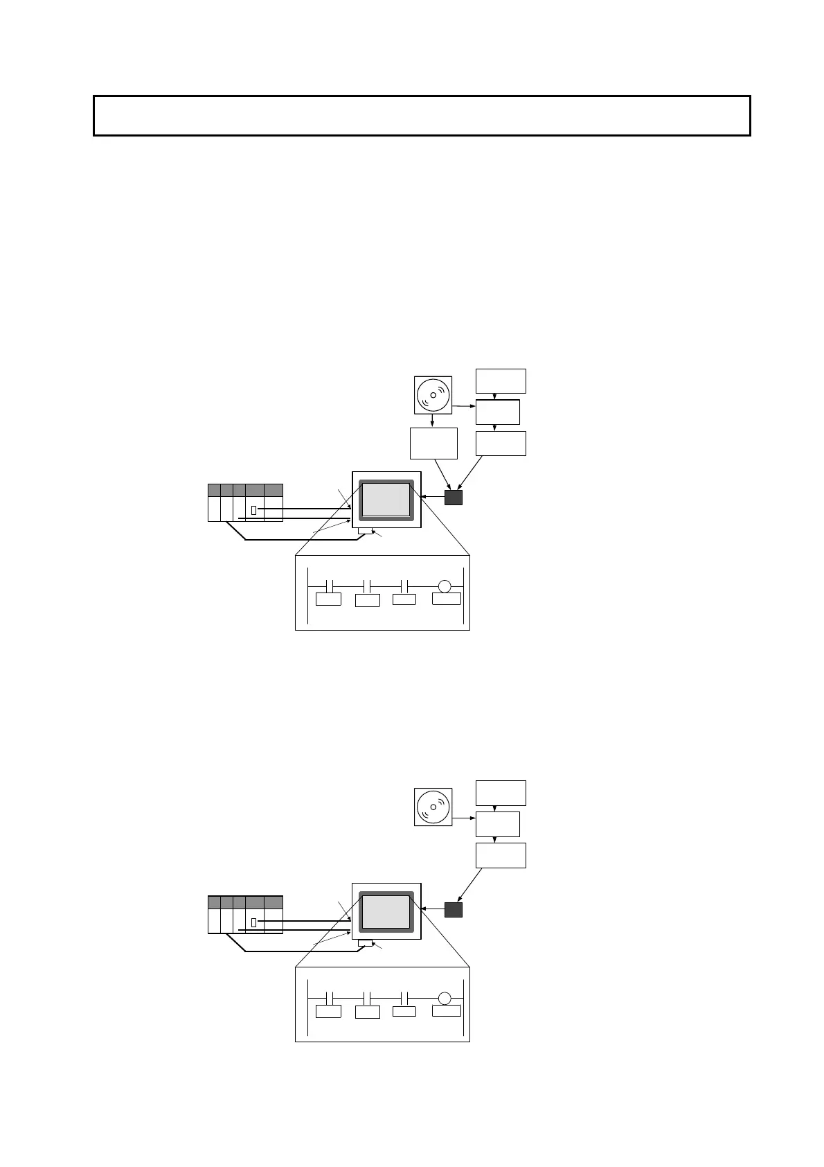
The Ladder Monitor can be started using the Special Screen Tab Page in the PT System
Menu when the system is configured with an NS-series PT connected to the host PLC by
RS-232C, Ethernet, or Controller Link communications. For pre-version-1 and version-1
NS-series PTs, however, a Memory Card containing the Ladder Monitor application must
be mounted at the back of the PT, as shown in the following diagram.
I/O comments can be read from a symbol table in the PLC. There is no need to copy I/O
comment files to a Memory Card when a symbol table is downloaded to a connected
PLC.
Pre-version-1 and Version-1 NS-series PTs
1:N NT Link
RS-232C
CD-ROM
NS-series PT
I/O Comment File
for Ladder Monitor
CX-Programmer
CXT File
Ladder Monitor
Application
I/O Comment
Extracting Tool
Install
Screen capture
data
Ethernet
CS/CJ-series
PLC (host)
Ladder Monitor (Started form the System Menu)
ER 0002.00
0000.01
0000.00
LAMP01
ER
SW2
SW1
Copy the
ldrdrmt
folder.
Copy the file to the
ldrdata
folder.
Serial Port A or B
Controller Link
Interface Unit
Controller Link
Ethernet Port
Memory Card
Version-2 NS-series PTs
For version-2 NS-series PTs (except for the NS5-V2) with system version 6.6 or higher,
the Ladder Monitor is built into the system program and thus a Memory Card is not
required except for the following operations:
Creating hard copies of screens (i.e., screen captures).
Displaying I/O comment files that were created using the I/O Comment Extracting Tool.
1:N NT Link
RS-232C
CD-ROM
NS-series PT
I/O Comment File
for Ladder Monitor
CX-Programmer
CXT File
I/O Comment
Extracting Tool
Install
Screen capture
data
Ethernet
CS/CJ-series
PLC (host)
Ladder Monitor (Started form the System Menu)
ER 0002.00
0000.01
0000.00
LAMP01
ER
SW2
SW1
Copy the file to the
ldrdata folder.
Serial Port A or B
Controller Link
Interface Unit
Controller Link
Ethernet Por
Memory Card

 Loading...


