EasyManua.ls Logo

Omron NT31

Omron NT31
313 pages
To Next Page IconTo Next Page
To Previous Page IconTo Previous Page
Loading...
89
Connecting to the Host’s RS-232C Port Section 5-1
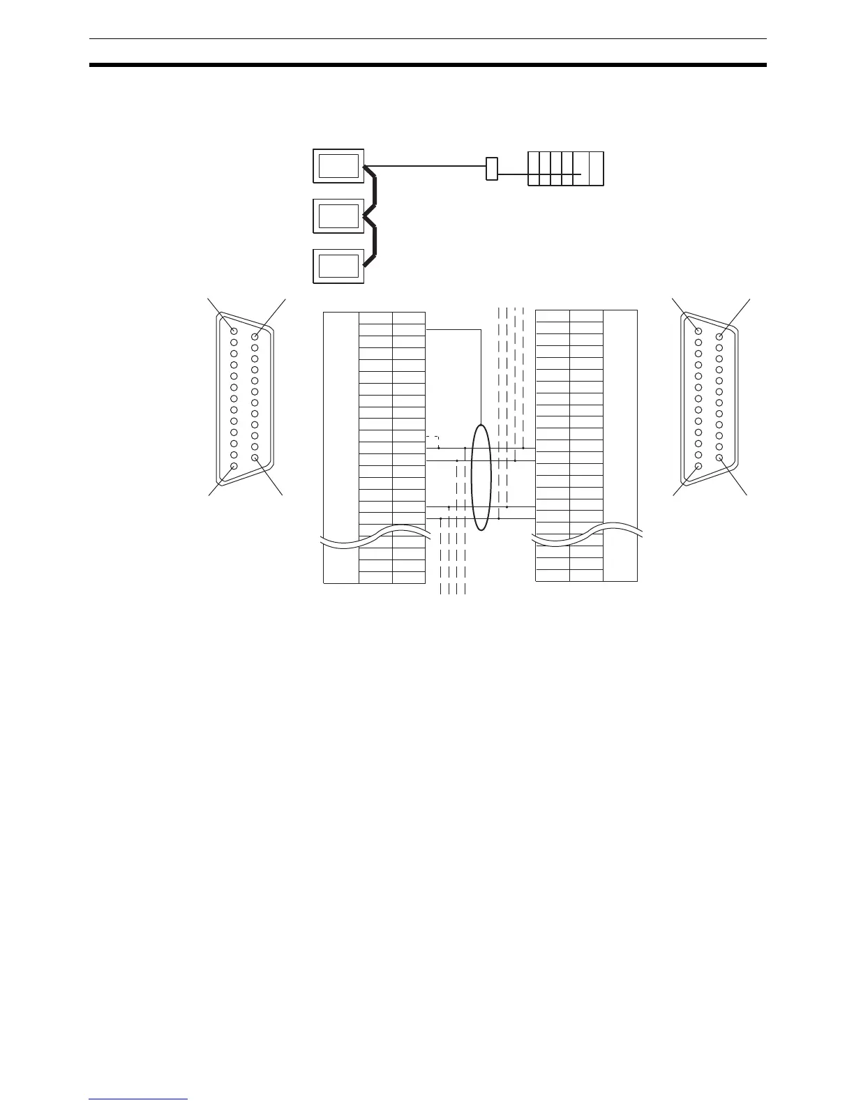
Connection between
NT31/NT31C Units (RS-
422A)
The relay terminal board is not included in the figure below. Insert a relay ter-
minal board so as to achieve the wiring configuration indicated below.
*2
Make the connection between pin numbers 9 and 10 at the terminal NT31/
NT31C (marked * in the figure above) only.
For details on handling shield wires, refer to 5-2-8 Handling the Shield on RS-
422A/485 Cables on page 128.
RS-422A
NT31/NT31C
Host
NT-AL001
1
14
13 25
1
1
4
13 25
Shielding wire
(
25-
p
in t
yp
e
)(
25-
p
in t
yp
e
)
NT31/NT31C side
FG
SD
RD
RS
CS
SG
TRM
RDB (+)
RDB (+)
SDA (-)
RDA (-)
RSB (+)
RSA (-)
1
2
3
4
5
6
7
8
9
10
11
12
13
14
15
16
23
24
25
Abbreviation
Pin number
RS-232C/
422A/485
connector
Connector
hood
NT31/NT31C side
FG
SD
RD
RS
CS
SG
TRM
RDB (+)
RDB (+)
SDA (-)
RDA (-)
RSB (+)
RSA (-)
1
2
3
4
5
6
7
8
9
10
11
12
13
14
15
16
23
24
25
Abbreviation
Pin number
RS-232C/
422A/485
connector
Connector
hood

Table of Contents

Other manuals for Omron NT31

Related product manuals