111
Connecting to the Host’s RS-422A/485 Port Section 5-2
• There are no Serial Communications Boards for the CQM1H in which port
1 is the RS-422A/485 port.
Setting the DIP Switches on a C200HX/HG/HE(-Z)E Communications
Board
Set the switches on a C200HX/HG/HE(-Z)E Communications Board as fol-
lows.
Switch 1: (4-wire = RS-422A), or
(2-wire = RS-485)
Switch 2: ON (terminator ON = terminating resistance enabled)
Setting Switches on a CQM1H Serial Communications Board
Set the switches on a CQM1H Serial Communications Board as follows.
2-wire or 4-wire selector (WIRE): (4-wire = RS-422A), or
(2-wire = RS-485)
Terminating resistance switch (TERM): ON (terminator ON = terminating
resistance enabled)
Connecting to CS-series Serial Communications Board
Serial Communications Board with RS-422A/485 port equipped for CS-series
CPU Unit:
CS1W-SCB41(-V1) (The port 2 is an RS-422A/485 port.)
Setting the Front Switches
Set the switches on the Serial Communications Board as shown below.
2-wire or 4-wire selector (WIRE): (4-wire = RS-422A), or
(2-wire = RS-485)
Terminating resistance switch (TERM): ON (terminator ON = terminating
resistance enabled)
4
2
4
2
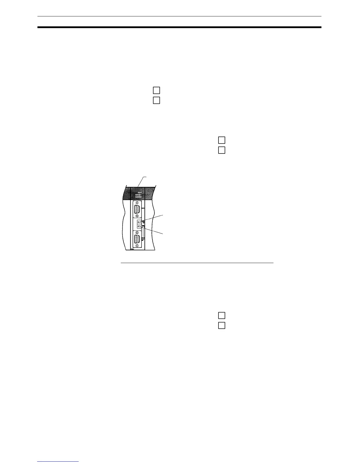
Serial Communications Board
(Inner Board slot 1)
Terminator Switch (TERM)
Set to ON (right side)
Wire Selection Switch (WIRE)
When using RS-422A: Set to 4 (right side) for 4-wire type.
When using RS-485: Set to 2 (left side) for 2-wire type.
4
2

 Loading...


