112
Connecting to the Host’s RS-422A/485 Port Section 5-2
Allocation DM Area Settings for CPU Unit
Settings are written from the Programming Device (a Programming Console
or CX-Programmer) directly into the allocation DM area (system setting area)
of the CPU Unit. After settings are written, they become effective by turning
the power ON, restarting the Unit, restarting the communications port, or exe-
cuting the STUP command.
In the following, the channel numbers of the allocation DM area and settings
are shown.
*1
Set any value between 0000 and 0009 hex for the baud rate. The same
baud rate will be used regardless of the value as long as it is between 0000
and 0009 hex.
For example, when connecting PTs with model numbers 3, 4, 5, and 6 to port
2 in the NT link (1:N), set a value of 8200 Hex for D32010, 0000 Hex for
DM32011, and 0006 Hex for D32016.
Connecting to a CS/CJ-series Serial Communications Unit
CS/CJ-series Rack-mounting Units:
CS1W-SCU31-V1 (Port 1 and port 2 are both RS-422A/485 ports.)
CJ1W-SCU31-V1 (Port 1 and port 2 are both RS-422A/485 ports.)
CJ1W-SCU41(-V1) (The port 1 is an RS-422A/485 port.)
Setting the Front Switches
Set the unit number of the Serial Communications Unit using the rotary
switches on the front of the Unit. Set the number or symbol in the setting dis-
play window in the following way using a flat-blade screwdriver. When using a
CS/CJ-series Serial Communications Unit set the switches as shown below.
2-wire or 4-wire selector (WIRE): (4-wire = RS-422A), or
(2-wire = RS-485)
Allocated DM
Area words
Setting Setting Contents
Port 2
DM32010 8200 1:N NT Link Mode
DM32011
0000 to 0009
(*1)
Baud rate (standard)
DM32016 000@@ = The highest unit number of the connected
PTs (0 to 7)
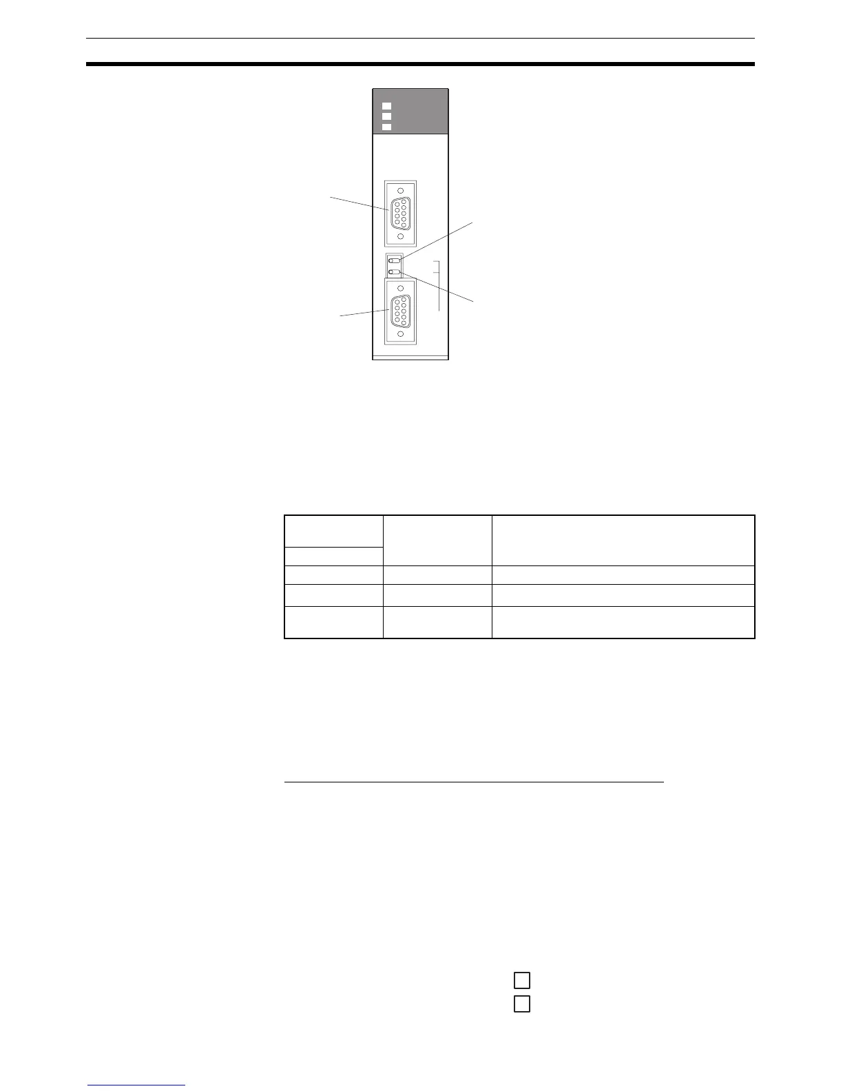
Port 1
RS-232C
Port 2
RS-422A/485
Terminal resistance setting switch (TER)
Set to ON (Terminal resistance is present.) (right side

 Loading...


