118
Connecting to the Host’s RS-422A/485 Port Section 5-2
Wiring When Connecting a CS-series Serial Communications Board, CS/
CJ-series Serial Communications Unit, C-series C200HX/HG/HE(-Z)E
Communications Board, CQM1H Serial Communications Board, or
CVM1/CV-series Host Link Unit
Applicable Units:
Note A Serial Communications Board cannot be used.
For details on handling shield wires, refer to 5-2-8 Handling the Shield on RS-
422A/485 Cables on page 128.
Wiring When Connecting a CVM1/CV-series CPU Unit
Applicable Units:
CVM1/CV-series CPU Units whose model names do not have the suffix -EV@
cannot be connected by any connection method.
CS1W-SCU31-V1
CJ1W-SCU31-V1/CJ1W-SCU41(-V1)
CS1G-CPU42/43/44/45-E(V1)
CS1H-CPU63/64/65/66/67-E(V1)
CS1G-CPU42H/43H/44H/45H
CS1H-CPU63H/64H/65H/66H/67H
CS1D-CPU65H/67H (See note.)
C200HE-CPU32/42-(Z)E
C200HG-CPU33/43/53/63-(Z)E
C200HX-CPU34/44/54/64-(Z)E
C200HX-CPU65-ZE/85-ZE
CQM1H-CPU51/61
CV500-LK201 (communications port 2)
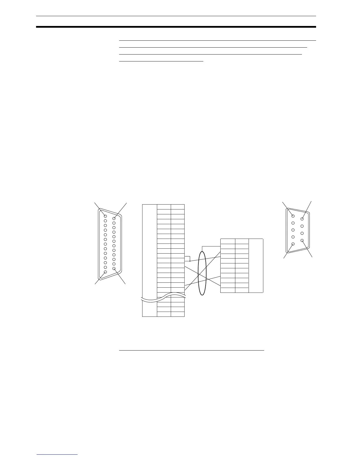
1
14
13 25
Shielding wire
6
5
9
1
NT31/NT31C side

 Loading...


