EasyManuals Logo

Omron NT31 Setup Manual

Omron NT31
313 pages
To Next Page IconTo Next Page
To Previous Page IconTo Previous Page
Page #142 background imageLoading...
Page #142 background image
125
Connecting to the Host’s RS-422A/485 Port Section 5-2
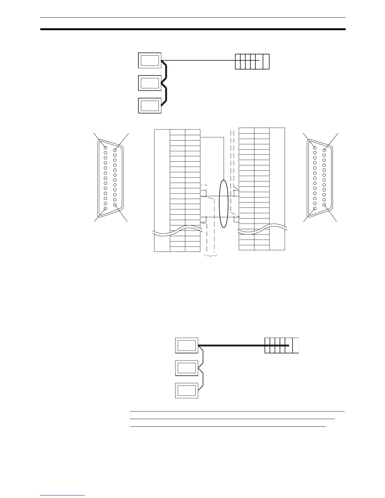
Connecting between NT31/NT31C Units
*2
Make the connection between pin numbers 9 and 10 at the NT31/NT31C at
the end of the RS-485 cable (marked * in the figure above) only.
For details on handling shield wires, refer to 5-2-8 Handling the Shield on RS-
422A/485 Cables on page 128.
Connecting an NT31/
NT31C and a Host
The relay terminal block is not included in this figure. Insert the relay terminal
block so as to achieve the wiring configuration shown below.
Wiring When Connecting a CS-series Serial Communications Board, CS/
CJ-series Serial Communications Unit, C-series C200HX/HG/HE(-Z)E
Communications Board, or CQM1H Serial Communications Board
Applicable Units:
Next PT
Shielding wire
RS-485
Host
1
14
13 25
1
1
4
13 25
NT31/NT31C
(25-pin type)
NT31/NT31C side
FG
SD
RD
RS
CS
SG
TRM
RDB (+)
RDB (+)
SDA (-)
RDA (-)
RSB (+)
RSA (-)
1
2
3
4
5
6
7
8
9
10
11
12
13
14
15
16
23
24
25
Abbreviation
Pin number
RS-232C/
422A/485
connector
Connector
hood
(25-pin type)
NT31/NT31C side
FG
SD
RD
RS
CS
SG
TRM
RDB (+)
RDB (+)
SDA (-)
RDA (-)
RSB (+)
RSA (-)
1
2
3
4
5
6
7
8
9
10
11
12
13
14
15
16
23
24
25
Abbreviation
Pin number
RS-232C/
422A/485
connector
Connector
hood
CS1W-SCU31-V1
CJ1W-SCU31-V1/CJ1W-SCU41(-V1)
RS-485
NT31/NT31C Host

Table of Contents

Other manuals for Omron NT31

Questions and Answers:

Question and Answer IconNeed help?

Do you have a question about the Omron NT31 and is the answer not in the manual?

Omron NT31 Specifications

General IconGeneral
BrandOmron
ModelNT31
CategoryTouch terminals
LanguageEnglish

Related product manuals