240
Responding to Displayed Error Messages Section 7-2
Send Errors
The following errors can occur when receiving data.
• Time out error
• Data over flow error
Probable Causes and
Remedies
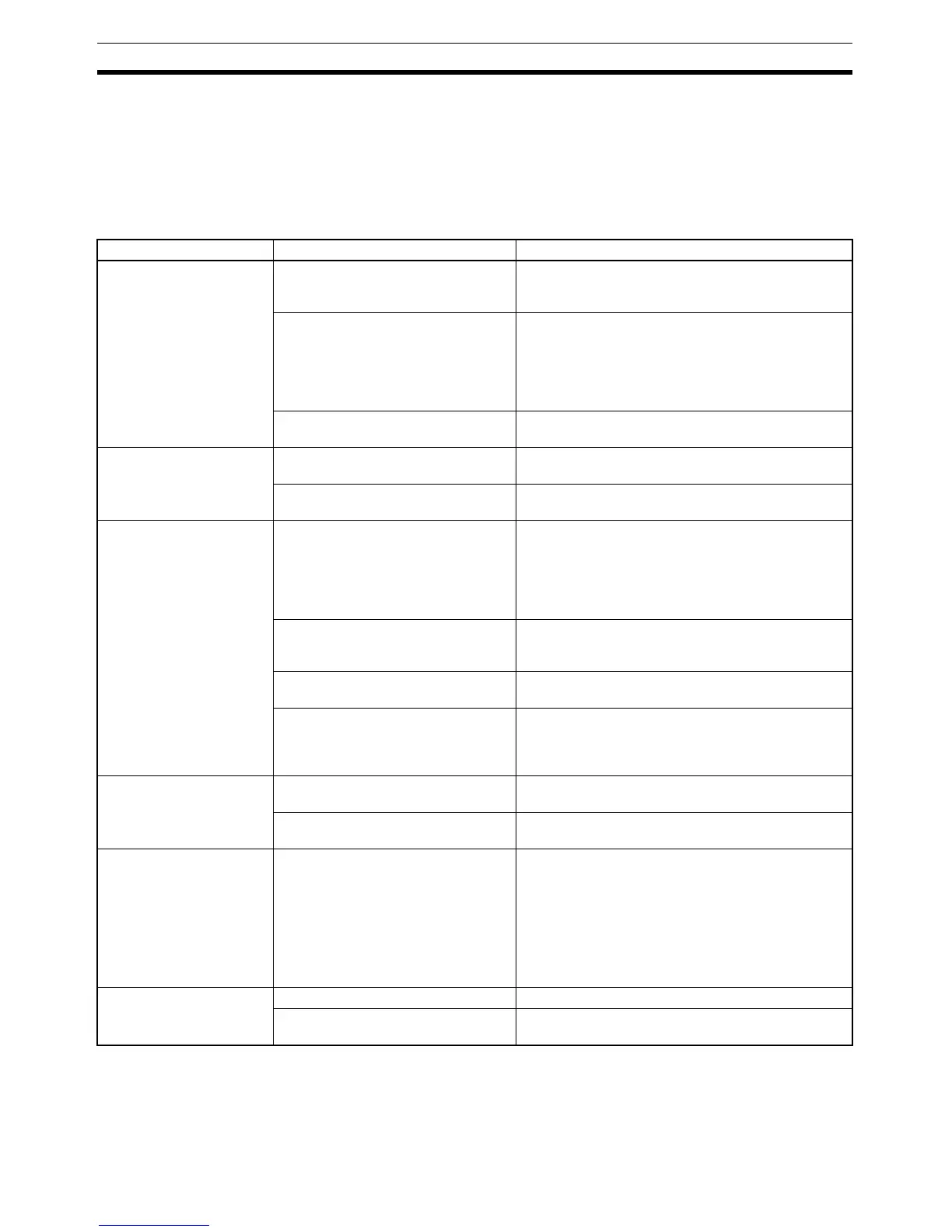
The remedies to take in accordance with the displayed cause are indicated in
the table below.
Error Details Displayed Probable Cause Remedy
Parity Error
Framing Error
Over-run Error
Communications parameters/
conditions set incorrectly.
Check if the settings at the host for parity bit, frame
length, communications speed, stop bit length and
flow control agree with those at the NT31/NT31C.
The connecting cables are not con-
nected correctly.
Check the communications cable connection and
perform a conductivity test. If there is a fault, replace
the cable. For details on communications cables,
refer to SECTION 4 Connecting to the Host from the
RS-232C Port, and SECTION 5 Connecting to the
Host from the RS-422A/485 Port.
Noise caused data corruption during
communications.
Carry out grounding work in accordance with the
conditions by referring to 3-1-4 Grounding, page 32.
FCS (Check Sum) Error Noise caused data corruption during
communications.
Carry out grounding work in accordance with the
conditions by referring to 3-1-4 Grounding, page 32.
The PLC is transmitting incorrect
data.
Check the operation at the host side.
Time-out Error The connecting cables are not con-
nected correctly. (Send/Receive)
Check the communications cable connection and
perform a conductivity test. If there is a fault, replace
the cable. For details on communications cables,
refer to SECTION 4 Connecting to the Host from the
RS-232C Port, and SECTION 5 Connecting to the
Host from the RS-422A/485 Port.
The communications service of the
host is stopped. (Send/Receive)
Check that the host is capable of communicating with
the NT31/NT31C (confirm that the communications
settings of the host and NT31/NT31C match).
Time-out Interval is too short. (Send) Set a longer value for Time-out Interval at the host
side.
Time-out Interval is too short.
(Receive)
Set a longer value for Time-out Interval in the System
Menu. (6-9-12 Setting the Time-out Interval,
page 186) It may also be possible to solve the prob-
lem by shortening the host cycle time.
PLC Unit No. Error The unit # does not match that set on
the PLC.
Re-set the unit number at the host side to 0.
Noise caused data corruption during
communications.
Carry out grounding work in accordance with the
conditions by referring to 3-1-4 Grounding, page 32.
NAK received —— Check the settings for allocated words and bits.
If noise is a possible factor, distance the cable from
sources of noise and insert a noise filter in the power
supply line.
If using the equipment in a location subject to a lot of
noise, use a cable with a high degree of protection
against noise for the transmission route. Also make
the cable as short as possible.
Undefined Command Error The host is not supported. Check the PLC model used for the host.
Instruction level 3 is not effective. Check that the instruction level setting for the host is
level 1, 2, 3.

 Loading...


