28
Names and Functions of Parts Section 2-2
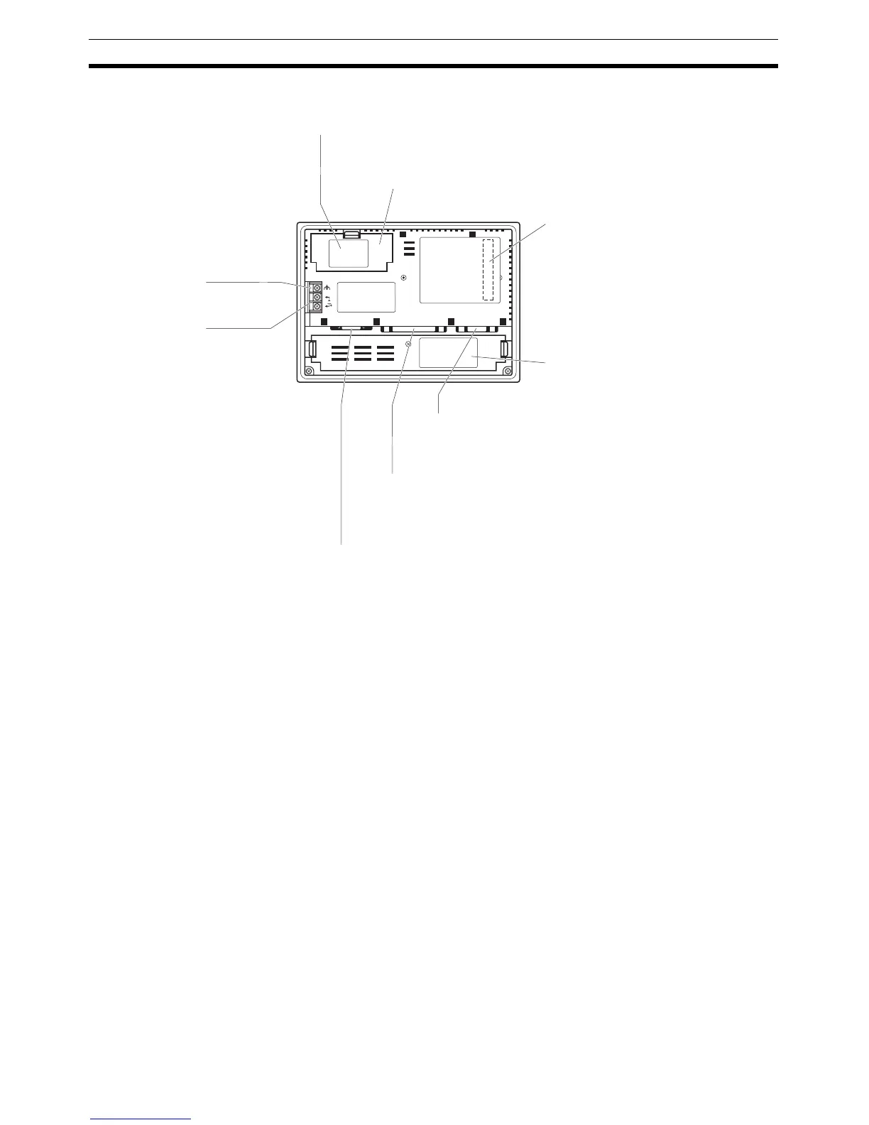
Rear View
Note Confirm system safety before turning the power ON/OFF or resetting.
Battery cover
The battery is secured underneath this cover.
Reset switch (inside the cover)
GR terminal
Power input terminals
Warning label
Serial port A connector
Serial port B connector
Printer connector
Used to initializes all the statuses of the NT31/NT31C.
However, registered data such as screen data, and memory switch
settings, retain their statuses before initialization.
Expansion interface connector
(under the label)
When using an expansion
interface unit such as a memory
unit, peel off the label and
connect it here.
Connect the cable for connection to the host or Support
Tool here. A bar code reader can also be connected
here. This is a 9-pin connector for RS-232C use only.
Connect the cable for connection to the host here. Depending on the
setting made at the NT31/NT31C system menu, either RS-232C or
RS-422A/485 may be used. This is a 25-pin connector.
It is not possible to use RS-232C and RS-422A/485 at the same time.
Connect the printer cable here.
Output conforms to Centronics specifications.
Connect the power to the
NT31/NT31C at these
terminals.
Grounding terminal to prevent
malfunction due to noise.
24V
DC
PRINTER PORT B PORT A

 Loading...


