54
Connecting to the RS-232C Port at the Host Section 4-1
Link Method (page 161).
Either set PLC Setup directly from a Programming Device (e.g. SYSMAC sup-
port software), or transmit the PLC Setup made at a Programming Device to
the CPU Unit.
For details on the PLC Setup, refer to the SYSMAC CVM1/CV500/1000/2000
Operation Manual: Ladder Diagrams (W202-E1-@).
Setting the Front Switches
C-series C200HS, C200HX/HG/HE(-Z)E, CPM1, CPM2A, CPM2C, CQM1,
CQM1H CPU Units, SRM1
The connection method depends upon the model of PLC being used, as
shown in the following table.
PLC model Connection method
C200HS, CQM1 Connect to the CPU Unit’s built-in RS-232C port.
C200HX/HG/HE(-Z)E • Connect to the CPU Unit’s built-in RS-232C port.
• Connect to one of the RS-232C ports (port A or port B) on a
Serial Communications Board.
CQM1H • Connect to the CPU Unit’s built-in RS-232C port.
• Connect to the peripheral port through a CS1W-CN118
Connecting Cable.
• Connect to the RS-232C port (port 1) on a Serial Communi-
cations Board.
CPM1 • Connect to the peripheral port through a CPM1-CIF01 RS-
232C Adapter.
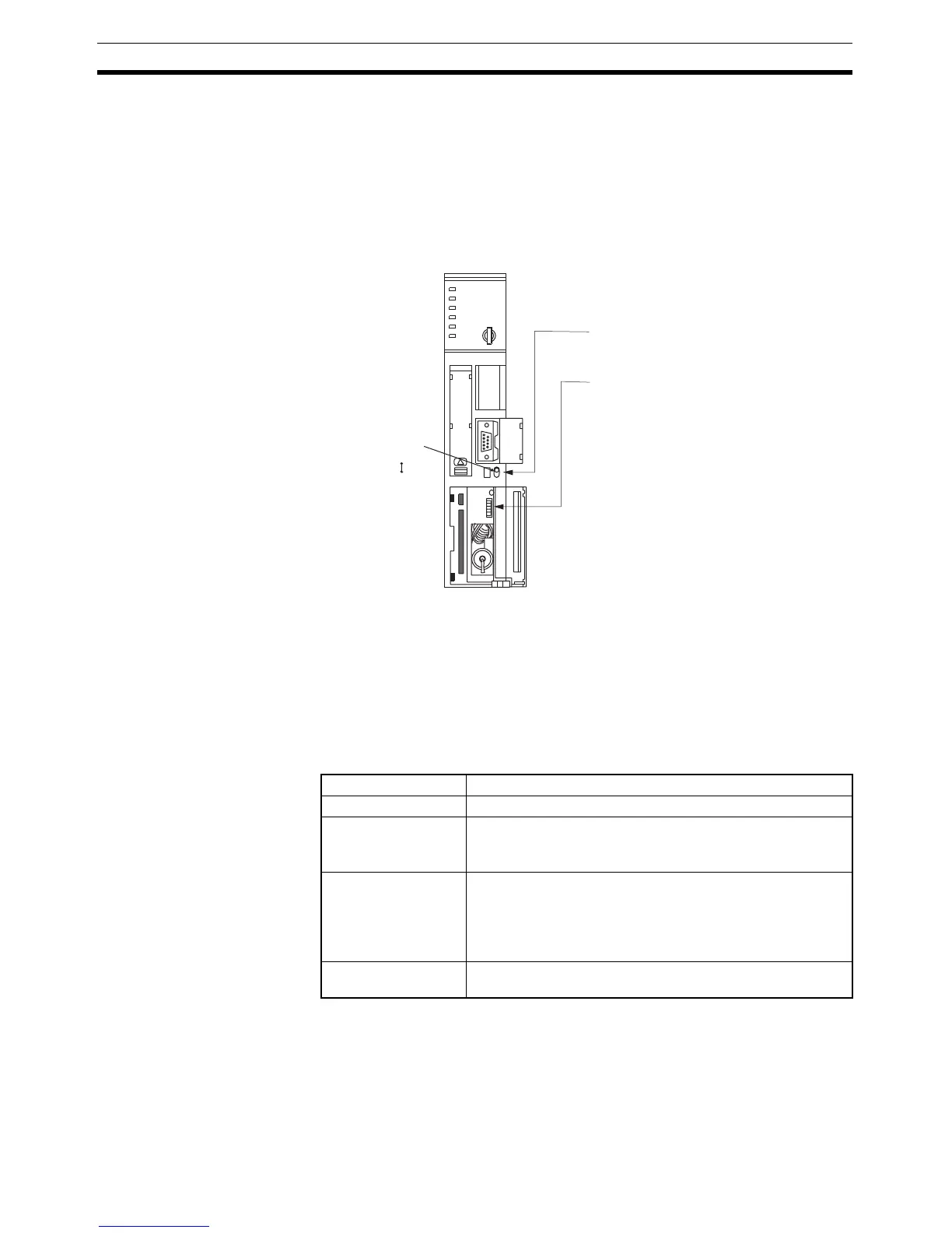
RS-232C
I/O port selector switch
RS-422A
• I/O port selection (selector switch)
Set this to RS-232C.
• System setting (DIP SW4)
Note
- DIP switch settings:
- PLC Setup:
To effect the existing DIP switch settings,
set SW4 to ON.
To effect the existing PLC Setup, set
SW4 to OFF.
For CPUs manufactured before or during
June 1995 (lot No. @@65), the existing
DIP switch settings differ from the
existing PLC Setup as follows.
2,400 bps, 1 stop bit, even parity, 7 bit
data length
9,600 bps, 2 stop bits, even parity, 7
bit data length
For CPUs manufactured from July 1995
onward (lot No. @@75), the stipulated
values in the DIP switch settings also are
9,600 bps and 2 stop bits.
 Loading...


