71
Connecting to the RS-232C Port at the Host Section 4-1
When connecting PTs with model numbers 0, 2, 3, 4, and 5 to the built-in RS-
232C port, for example, set the value 8200 Hex to word 160, 000A Hex to
word 161, and 0005 Hex to word 166.
Either set PLC Setup directly from a Programming Device (Programming Con-
sole), or transmit the PLC Setup made at a Programming Device (CX-Pro-
grammer) to the CPU Unit.
For details on the PLC Setup, refer to the CS-series Operation Manual
(W339) or the SYSMAC CJ Series Operation Manual (W393).
Reference: When using the CX-Programmer to set the high-speed 1:N NT Link, set the
communications baud rate to 115,200 bps.
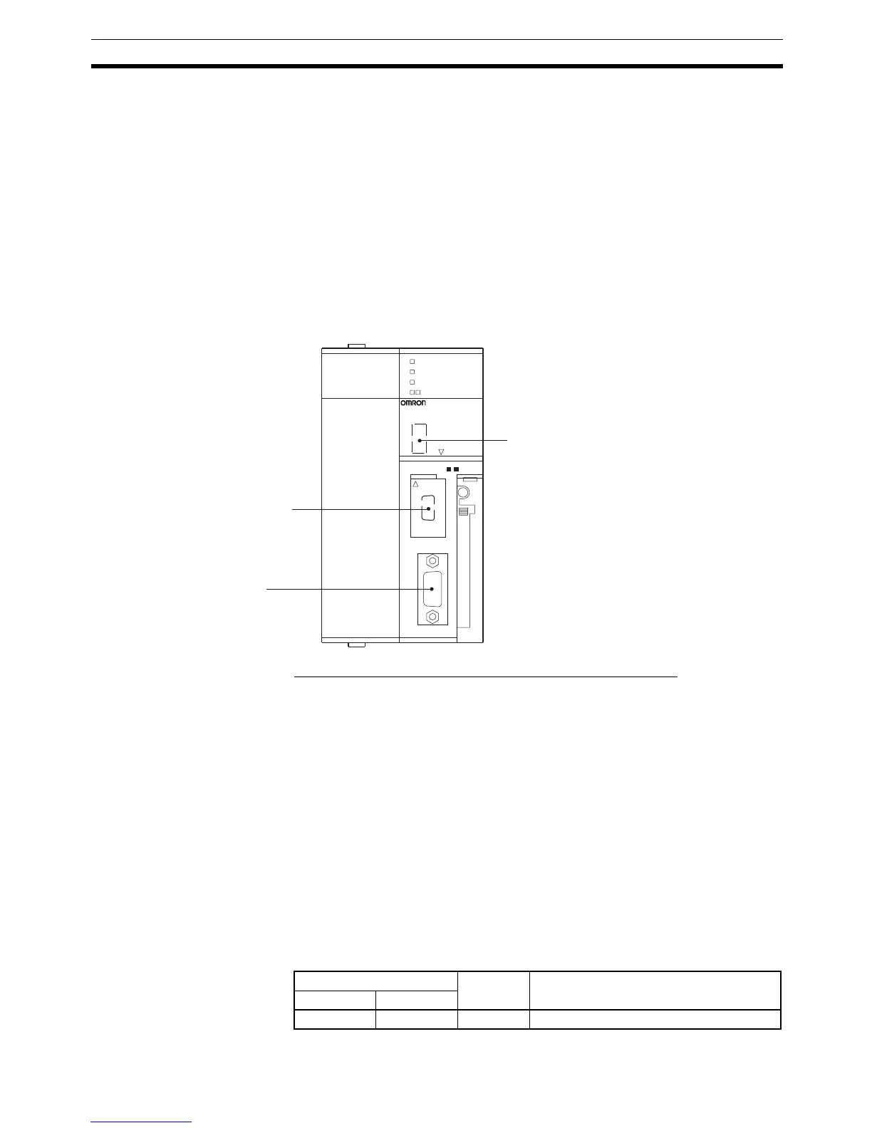
Setting the Front Switches
Set the CPU Unit’s DIP switch to 4 or 5 in accordance with the port NT31/
NT31C is connected to. An example of a CS-series CPU Unit is shown below.
Connecting to a CS-series Serial Communications Board
Serial Communications Board equipped with a RS-232C port for CS-series
CPU Units: CS1W-SCB21(-V1)/CS1W-SCB41(-V1)
Note Cannot be used with the CS1D-CPU65H/67H.
Reference: CS-series Serial Communications Boards and Units with lot number 991220
(December 20, 1999) or later support the high-speed 1:N NT Link method.
Boards and Units with earlier lot numbers cannot be used.
CPU Unit Allocation DM Area Settings
Setting is written from the Programming Device (a Programming Console or
CX-Programmer) directly into the allocation DM area (system setting area) of
the CPU Unit. After the setting is written, it becomes effective by turning the
power ON, restarting the Unit, restarting the communications port, or execu-
tion of the STUP command.
In the following, the channel numbers of the allocation DM area and settings
are shown.
Peripheral port
RS-232 port
DIP switches (inside the battery storage)
SYSMAC CS1G
PROGRAMMABLE CONTROLLER
CPU42
OPEN
OPEN
PERIPHERAL
PORT
BUSY
RUN
ERR/ALM
INH
PRPHL/COMM
MCPWR
This is used mainly for
connection to the
Programming Device.
(This also supports
connection of RS-232C
devices.)
This is used mainly
for connection of RS-
232C devices.
(This also supports
the connection of
CX-Programmer.)
• Set SW4 to ON (establishing communications in
accordance with PLC Setup) when connecting
the NT31/NT31C to the peripheral port.
• Set SW5 to OFF (establishing communications
in accordance with PLC Setup) when connecting
the NT31/NT31C to the RS-232C port.
Allocated DM Area words Setting Setting Contents
Port 1 Port 2
DM32000 DM32010 8200 NT link (1:N) mode

 Loading...


