77
Connecting to the RS-232C Port at the Host Section 4-1
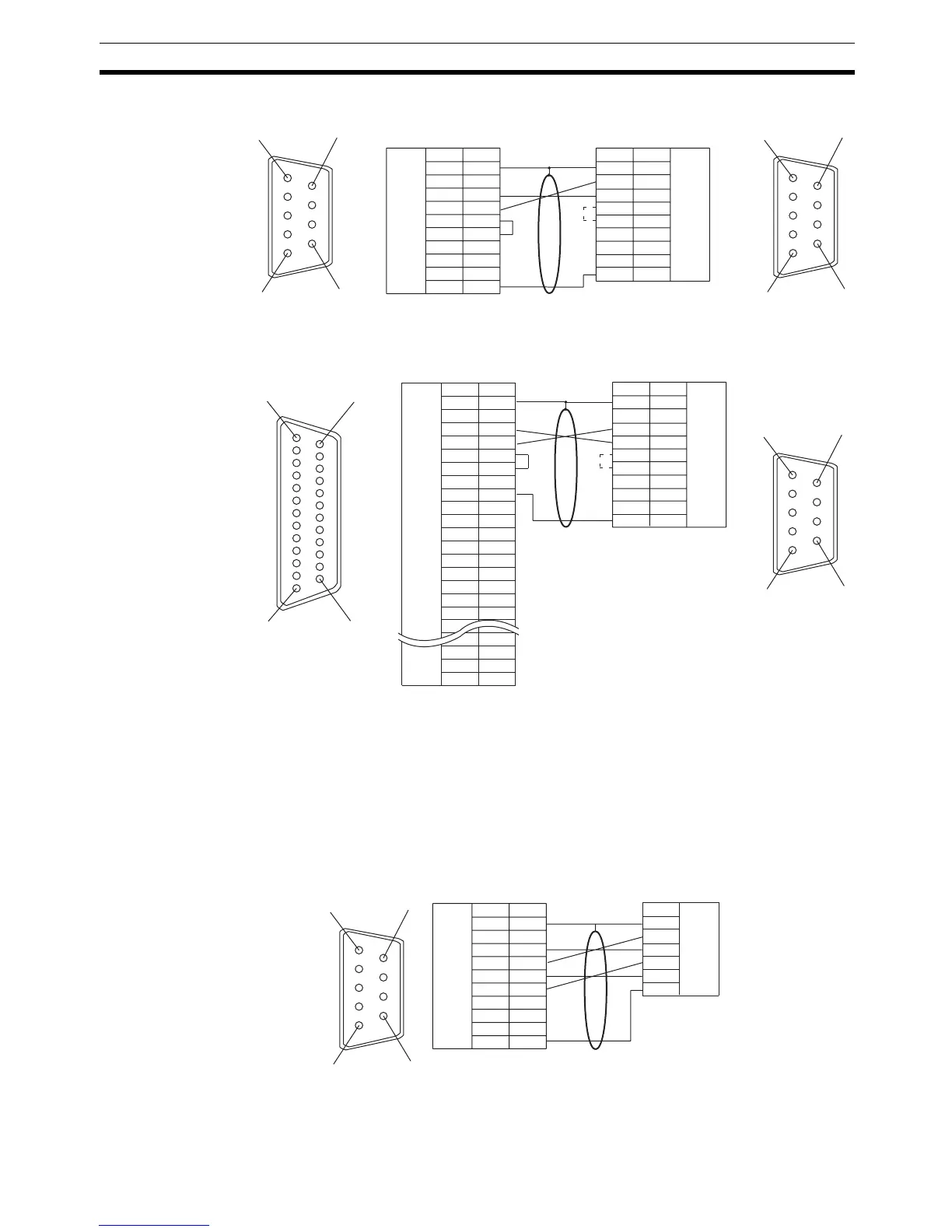
Serial Port A
Serial Port B
* In case 0 V is set for a Unit which has CTS setting selector, it is not neces-
sary to shorten between RS and CS.
Wiring for a Memory Link
Connection
Cables with connectors that can be used at serial port A:
CV500-CN228 (9-pin
⇔25-pin, 2 m)
XW2Z-S002 (9-pin
⇔9-pin, 2 m)
Serial Port A
Prepare the adapter cable while referring to the following diagram.
Serial Port B
Prepare the adapter cable while referring to the following diagram.
1
6
5
9
1
6
5
9
FG
+5V
CS
RS
RD
SD
SG
1
2
3
4
5
6
7
8
9
1
2
3
4
5
6
7
8
9
-
-
-
FG
+5V
CS
RS
RD
SD
SG
DSR
ER
NT31/NT31C PLC (Host link unit)
(9-pin type)
Shielding wire
(9-pin type)
*
Abbreviation
RS-232C
interface
Pin
number
Connector
hood
Abbreviation
Pin
number
RS-232C
interface
1
6
5
9
114
13 25
*
NT31/NT31C PLC (Host link unit)
FG
CS
RS
RD
SD
TRM
-
-
SG
-
-
SDA (-)
RDA (-)
-
RDB (+)
SDB (+)
-
-
-
RSB (+)
RSA (-)
1
2
3
4
5
6
7
8
9
10
11
12
13
14
15
16
-
23
24
25
-
1
2
3
4
5
6
7
8
9
(9-pin type)
FG
CS
RS
RD
SD
-
-
SG
-
-
(25-pin t

 Loading...


