3-30
3-1 Servo Drive Specifications
OMNUC G5-series AC Servomotors and Servo Drives User’s Manual (with Built-in EtherCAT Communications)
3
Specifications
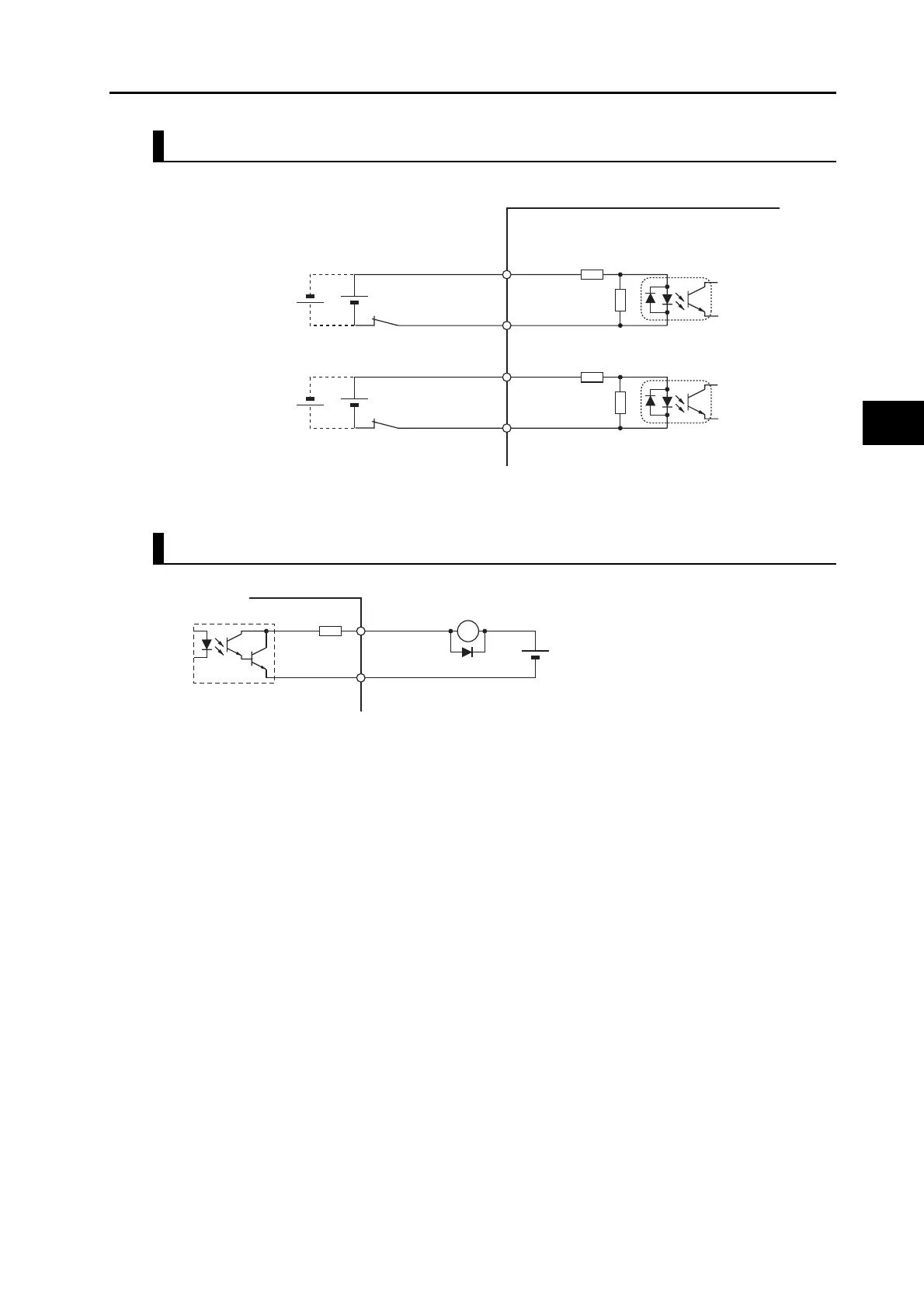
Safety Input Circuits
EDM Output Circuit
Note: When driving a relay directly with an output signal, always insert a diode as shown in the above
figure.
Servo Drive
External power supply
12 VDC ± 5% to
24 VDC ± 5%
Signal level
ON level: 10 V min.
OFF level: 3 V max.
4.7 kΩ
1.0 kΩ
SF1+ 4
SF1- 3
SF2+ 6
SF2- 5
Photocoupler
input
4.7 kΩ
1.0 kΩ
Photocoupler
input
External power supply
12 to 24 VDC
Maximum service voltage: 30 VDC or less
Maximum output current: 50 mA max.
Leakage current: 0.1 mA max.
Residual voltage: 1.7 V max.
Di: Surge voltage prevention diode
(Use a high-speed diode.)
7 -EDM
8 +EDM
Di
10 Ω
Servo Drive
X

 Loading...


