6-18
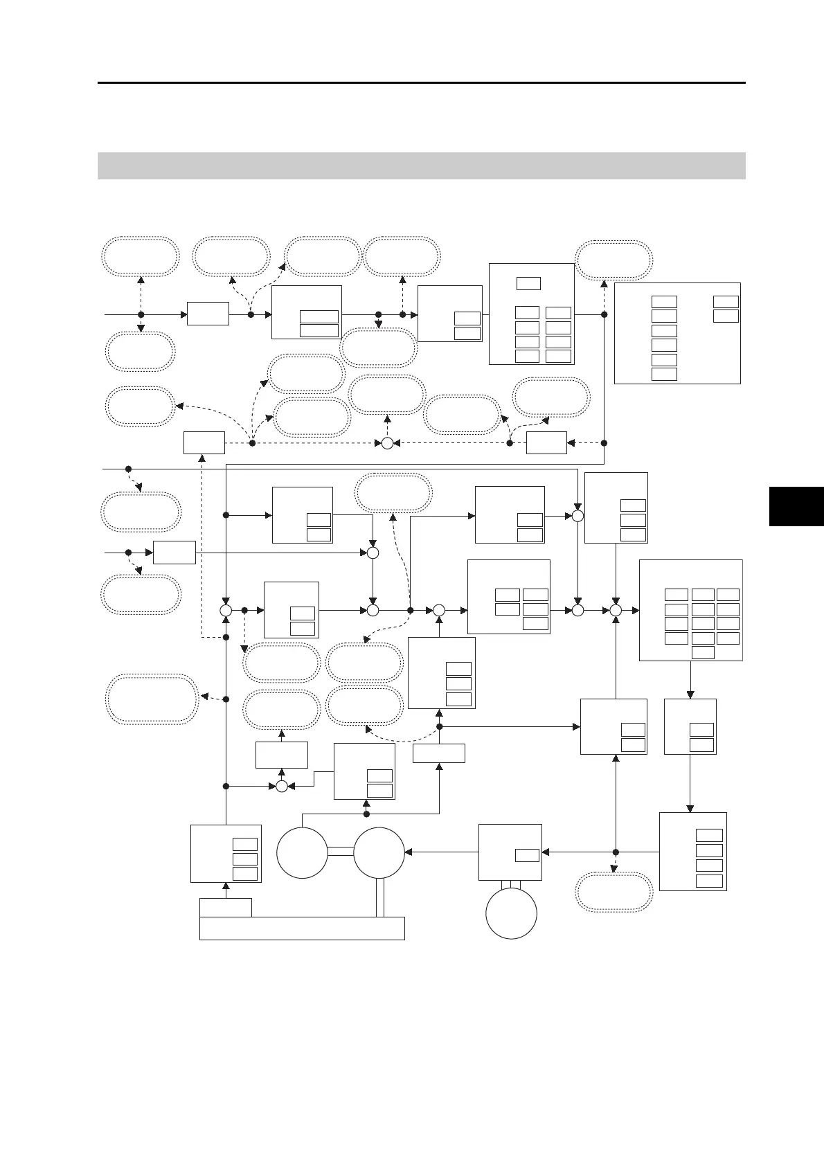
6-6 Fully-closed Control
OMNUC G5-series AC Servomotors and Servo Drives User’s Manual (with Built-in EtherCAT Communications)
6
Drive Profile
Parameter Block Diagram for Fully-closed Control Mode
The following is a block diagram for fully-closed control using an R88D-KN@@@-ECT-Series
Servo Drive.
Note 1: Numbers within parentheses are sub-index numbers.
Note 2: Numbers within boxes are hexadecimal index numbers.
+
-
3100
3105
+
++
-
3623
3624
3104
3109
3521
60E0
60E1
3611
+
+
++
+
3103
3108
3610
3203
3206
3209
3212
3202
3205
3208
3211
3201
3204
3207
3210
3200
3102
3107
3101
3106
3004
3323
3326
3327
3325
3324
+-
6091(01)
6091(02)
3818
3222
3218
3118
3217
3219
3220 3221
+
-
3607
3608
3609
3112
3113
3110
3111
+
+
6072
3213
3214
3216
3215
3119
3605
3606
3114
3115
3116
3117
External encoder
+
+
Speed
Feed-forward
Gain
Filter
FIR
Position
Control
1
2
1
2
3
4
Setting 2
Mode
Delay Time
Level
Hysteresis
Switching Time
Setting 3
Ratio
Notch Filter
DepthWidth
1
2
3
4
Frequency
Adaptive Filter Selection
Linear Integral
Inertia Ratio
1
2
MAX
607A hex
Target position
[command units]
6062 hex
Position demand
value [command
units]
4015 hex
Velocity Demand
Value [command
units/s]
4016 hex
Motor Velocity
Demand Value
[r/min]
4017 hex
Motor Velocity
Demand Value After
Filtering [r/min]
Generate
Position
Command
Gear ratio forward
conversion
Numerator
Denominator
Smoothing
filter
First-order
Lag
Damping Control
Switch
Selection
Frequency
Filter
Gain Switching
6081 hex
Profile Velocity
[command
units/s]
60BA or 60BC hex
Touch probe pos
1/2 pos value
[command units]
606C hex
Velocity actual
value [command
units/s]
6064 hex
Position actual
value [command
units]
60F4 hex
Following error
actual value
[command units]
4018 hex
Position Demand
Value After Filtering
[command units]
401F hex
Velocity Demand
Value After Filtering
[command units/s]
Electronic
gear reverse
conversion
Electronic
gear reverse
conversion
60B2 hex
Torque offset
[0.1%]
60B1 hex
Velocity offset
[command units/s]
60FA hex
Control effort
[command units/s]
Torque
Feed-forward
Gain
Filter
Friction
Compensation
Offset Value
Forward
Reverse
Speed FF
unit
conversion
Speed Control
401D hex
Fully-closed Following
Error [external encoder
pulses]
401A hex
Motor Control
Effort [r/min]
Speed
Detection Filter
Expansion
Setting
1
2
6063 hex
Position actual
internal value
[external encoder
pulses]
401B hex
Motor Velocity Actual
Value [r/min]
Disturbance
Observer
Gain
Filter
1
2
Torque
Filter
Speed detection
Encoder
Motor
Current control
Response
Setting
Main
power
supply
6074 or 6077 hex
Torque demand or
Torque actual value
[0.1%]
Torque Limit
Selection
Positive
Negative
Electronic
gear reverse
conversion
401E hex
Hybrid Following
Error [command
units]
Input setting
Type
Reverse
Phase Z
disabled
External Encoder
reverse dividing
Denominator
Numerator
60FC hex
Position demand
internal value
[encoder pulses]

 Loading...


