3-29
3-1 Servo Drive Specifications
OMNUC G5-series AC Servomotors and Servo Drives User’s Manual (with Built-in EtherCAT Communications)
3
Specifications
Safety Connector Specifications (CN8)
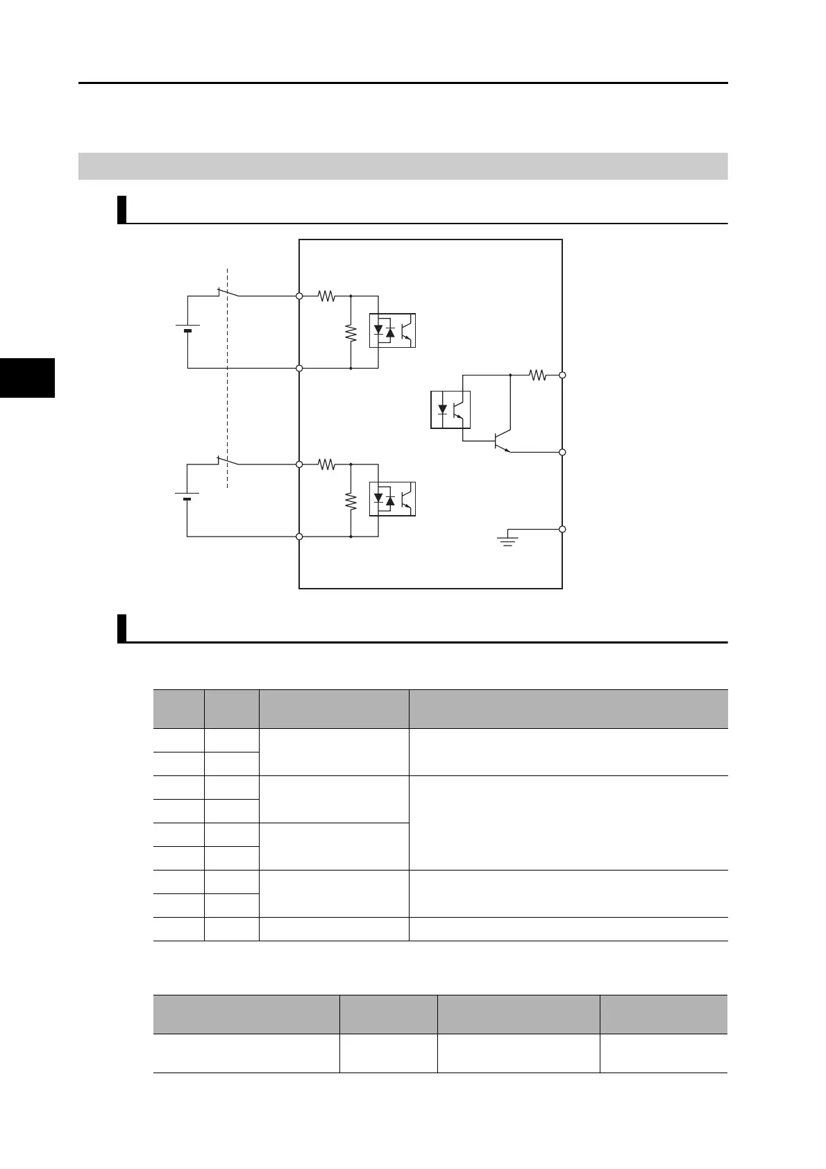
Connection of Safety I/O Signals and Processing of External Signals
Safety I/O Signal Table
Safety I/O (CN8)
Connector for CN8 (8 pins)
SF1+
12 to 24 VDC
SF1-
4
3
SF2+
12 to 24 VDC
SF2-
6
8
EDM+
EDM-
FG
7
5
10 Ω
4.7 kΩ
1 kΩ
4.7 kΩ
1 kΩ
Maximum service voltage:
30 VDC or less
Maximum output current:
50 mADC
Shell
Leakage current: 0.1 mA max.
Residual voltage: 1.7 V max.
Pin
No.
Sym-
bol
Name Function and interface
1 - Reserved Do not connect.
2-
3SF1− Safety input 1 Inputs 1 and 2 for operating the STO function, which are
2 independent circuits. This input turns OFF the power
transistor drive signals in the Servo Drive to cut off the
current output to the motor.
4SF1+
5SF2− Safety input 2
6SF2+
7EDM− EDM output A monitor signal is output to detect a safety function
failure.
8EDM+
Shell FG Frame ground Connected to the ground terminal inside the Servo Drive.
Name Model Manufacturer
OMRON model
number
Industrial Mini I/O Connector
(D-SHAPE1)
2013595-1 Tyco Electronics AMP KK R88A-CNK81S

 Loading...


