3-71
3-4 Cable and Connector Specifications
OMNUC G5-series AC Servomotors and Servo Drives User’s Manual (with Built-in EtherCAT Communications)
3
Specifications
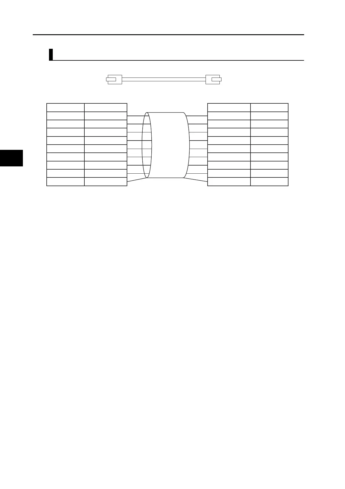
Attaching the Connectors to the Cable
Use straight wiring for the communications cable, as shown below.
Note 1: Connect the cable shield to the connector hood at both ends of the cable.
Note 2: There are two connection methods for Ethernet: T568A and T568B. The T568A connection
method is shown above, but the T568B connection method can also be used.
1
2
3
4
5
6
7
8
1
2
3
4
5
6
7
8
Wire color
White-Green
Green
White-Orange
Blue
White-Blue
Orange
White-Brown
Brown
Shield
Connector hood
Pin No.
Wire color
White-Green
Green
White-Orange
Blue
White-Blue
Orange
White-Brown
Brown
Shield
Connector hood
Pin No.

 Loading...


