3-79
3-4 Cable and Connector Specifications
OMNUC G5-series AC Servomotors and Servo Drives User’s Manual (with Built-in EtherCAT Communications)
3
Specifications
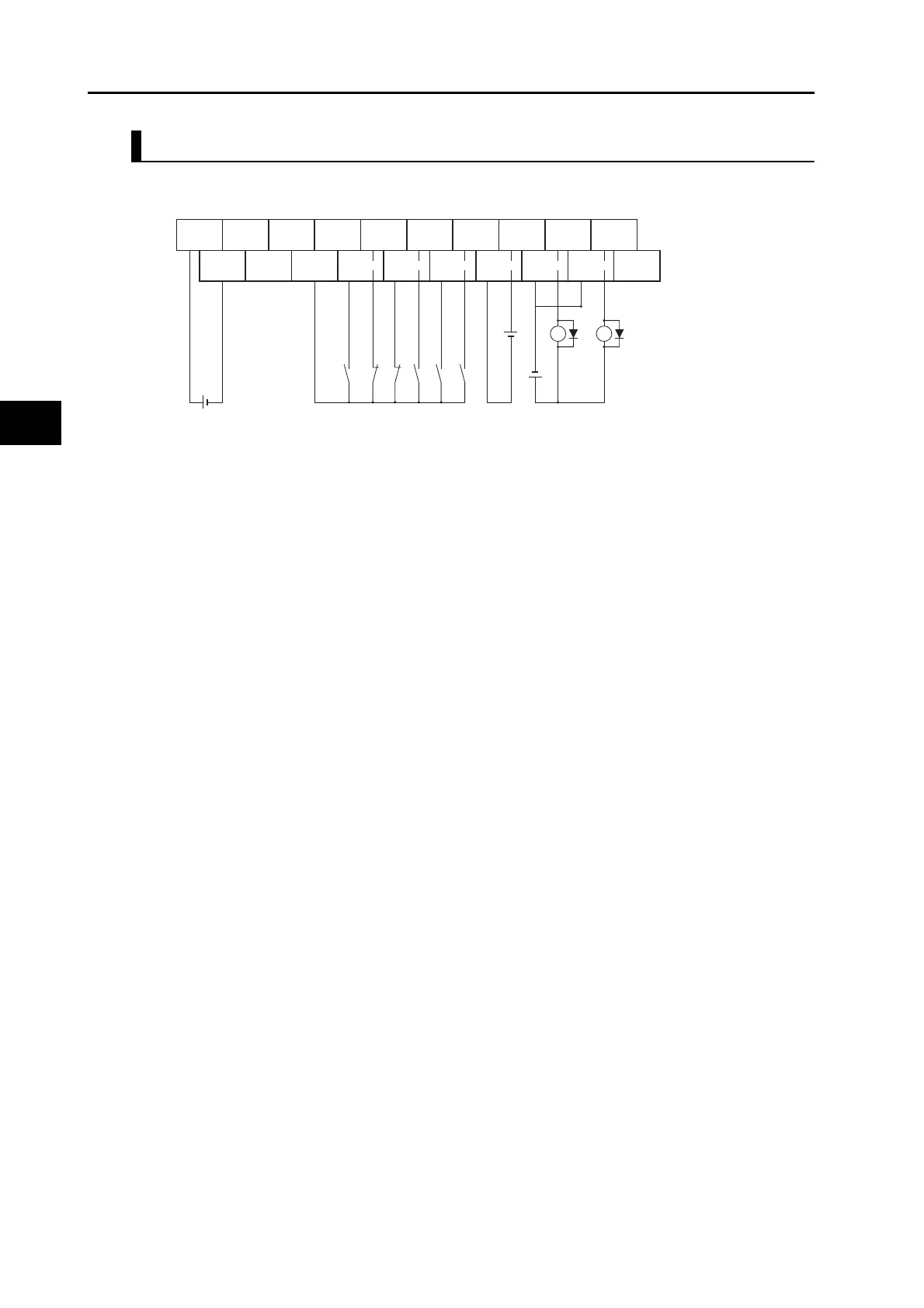
Terminal Block Wiring Example
The example is for the XW2B-20G4, XW2B-20G5, and XW2D-20G6.
*1. Assign the brake interlock output (BKIR) to pin CN1-1.
*2. This is the absolute encoder backup battery of 2.8 to 4.5 V. Secure the battery in place using cable
clips with double-sided adhesive tape. Connect the battery to either the connector terminal block or
the absolute encoder backup battery cable (with a battery). The absolute encoder backup battery is
not required when the Servomotor is equipped with an incremental encoder.
*3. The XB contact is used to turn ON/OFF the electromagnetic brake.
+24 V
0 V
+24 V +24 V POT EXT3 EXT1 BAT BKIR ALM
0 V 0 V DEC EXT2
BATGND
NOT
BKIRCOM
FG
24 VDC 24 VDC
*3
*2
*1
ALMCOM
XB X1
STOP
 Loading...


