4-7
4-2 Wiring
OMNUC G5-series AC Servomotors and Servo Drives User’s Manual (with Built-in EtherCAT Communications)
4
System Design
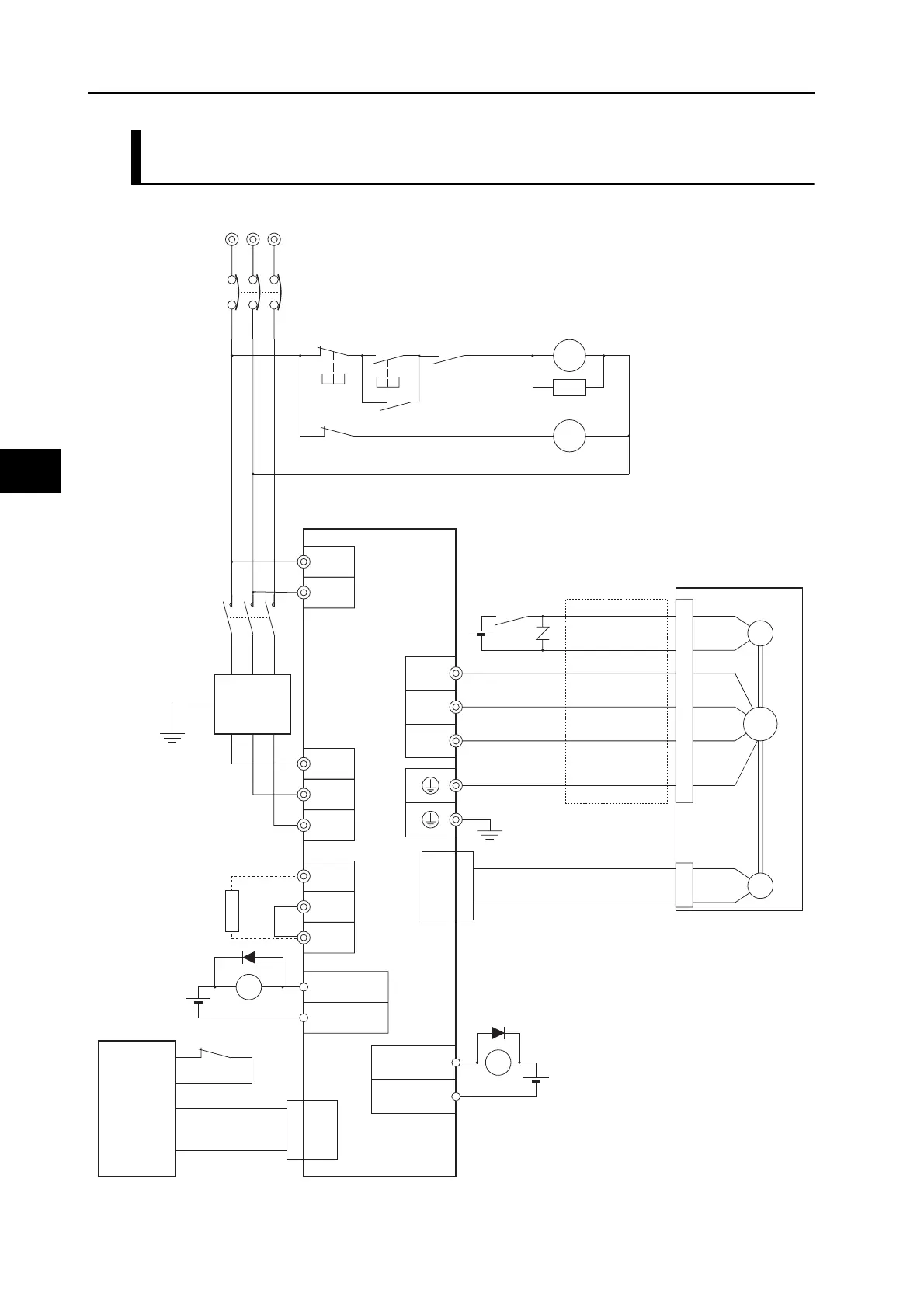
R88D-KN01H-ECT-R/-KN02H-ECT-R/-KN04H-ECT-R/-KN08H-ECT-R/
-KN10H-ECT-R/-KN15H-ECT-R (3-phase Input)
3-phase 100 to 120 VAC, 50/60 Hz: R88D-
KN@@L-ECT-R
3-phase 200 to 240 VAC, 50/60 Hz: R88D-
KN@@H-ECT-R
*1. A recommended product is listed in 4-3,
Wiring Confirming to EMC Directives.
*2. Recommended relay: MY relay by
OMRON (24-V) For example, MY2 relay
by OMRON can be used with all
G5-series motors with brakes because its
rated inductive load is 2 A (24 VDC).
*3. There is no polarity on the brakes.
*4. Models with a built-in Regeneration
Resistor (
KN08H-ECT-R to KN15H-ECT-R)
have B2 and B3 connected. When the
amount of regeneration is large, remove
the connection between B2 and B3 and
connect a Regeneration Resistor
between B1 and B2.
RT
NFB
S
Noise filter (*1)
123
456
E
NF
Ground to 100 Ω
or less
Main circuit contactor (*1)
Servo error display
L1C
L2C
L1
L2
L3
OMNUC G5-Series
AC Servo Drive
ALMCOM
/ALM3
4
User-side
control
device
CN1
X
24 VDC
1
2
BKIR
BKIRCOM
XB
24 VDC
Control cables
OMNUC G5-Series
AC Servomotor
W
V
U
B
E
M
CN2
Encoder cables
Power cables
24 VDC
(*3)
(*2)
CN1
CN1
B1
B3
B2
(*4)
Regeneration
Resistor
CNB
CNB
CNA
CNA
Ground to 100 Ω or less
XB
X
Surge suppressor
(*1)
Main circuit power supply
1MC
1MC
PL
OFF
X
ON
X
1MC

 Loading...


