4-17
4-2 Wiring
OMNUC G5-series AC Servomotors and Servo Drives User’s Manual (with Built-in EtherCAT Communications)
4
System Design
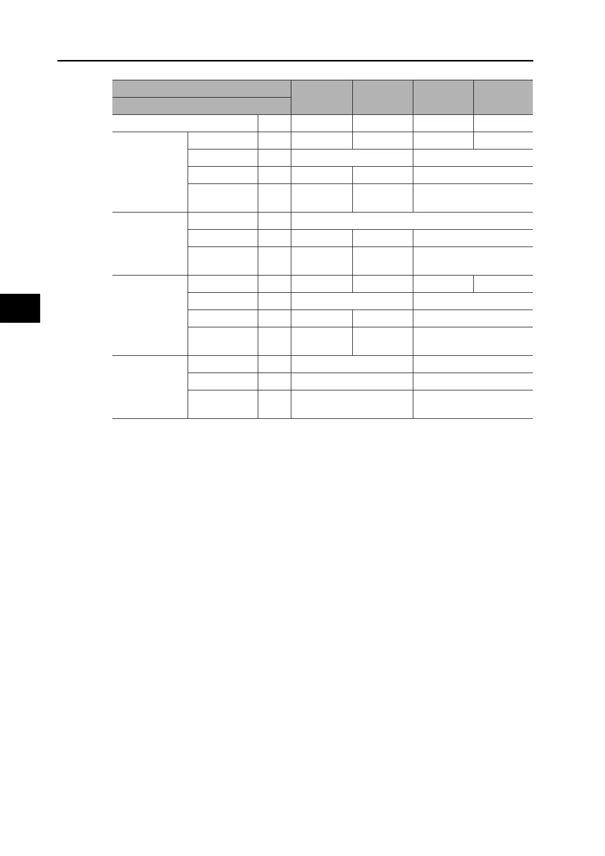
*1. The first value is for single-phase input power and the second value is for 3-phase input power.
*2. Connect an OMRON power cable to the motor connection terminals.
*3. Use the same wire size for B1 and B2.
Model (R88D-)
KN15H-
ECT-R
KN20H-
ECT-R
KN30H-
ECT-R
KN50H-
ECT-R
Item Unit
Power supply capacity kVA 2.3 3.3 4.5 7.5
Main circuit
power supply
input (L1 and L3,
or L1, L2 and L3)
Rated current A 14.2/8.1
*1
11.8 15.1 21.6
Wire size − AWG14 AWG12
Screw size −− − M5
Tightening
torque
N·m −− 2.0
Control circuit
power supply
input (L1C and
L2C)
Wire size − AWG18
Screw size −− − M5
Tightening
torque
N·m −− 2.0
Motor
connection
terminals (U, V,
W, and FG)
*2 *3
Rated current A 9.4 13.4 18.7 33.0
Wire size − AWG14 AWG12
Screw size −− − M5
Tightening
torque
N·m −− 2.0
Frame ground
(FG)
Wire size − AWG14 AWG12
Screw size − M4 M5
Tightening
torque
N·m 1.2 2.0
 Loading...


