4-23
4-3 Wiring Conforming to EMC Directives
OMNUC G5-series AC Servomotors and Servo Drives User’s Manual (with Built-in EtherCAT Communications)
4
System Design
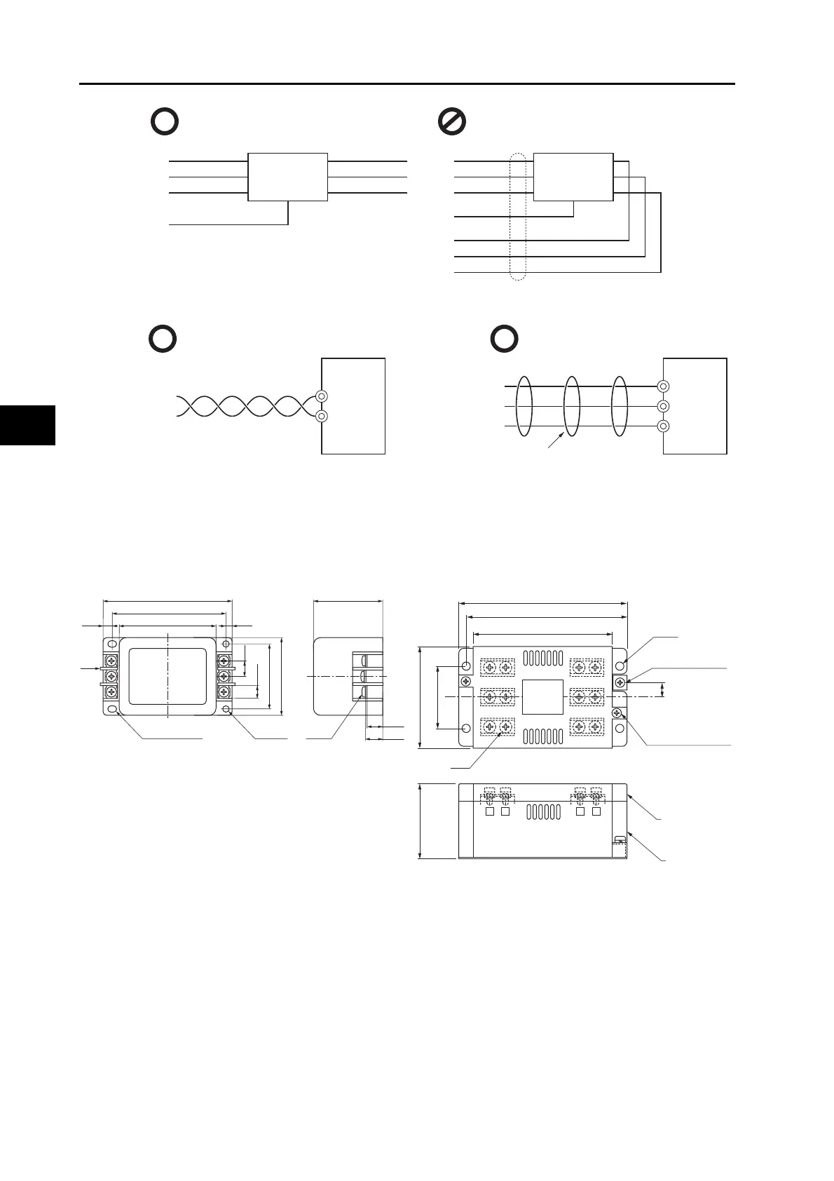
Use twisted-pair cables for the power supply cables, or bind the cables.
Separate power supply lines and signal lines when wiring.
External Dimensions
SUP-EK5-ER-6 3SUP-HU10-ER-6
Separate the input and output. The effect of the noise filter is small.
NF
1
2
3
4
5
6
E
NF
1
2
3
4
5
6
E
AC input AC input
Ground
Ground
AC output
AC output
Twisted-pair cables Bound cables
Servo Drive
L1C
L1
L2
L3
L2C
Servo Drive
Binding
50.0
60.0
12.0
10.0
11.6
13.0
75.07.0
2.0
88.0
100±2.0 53.1±1.0
5.0
2-φ4.5×6.75
2-φ4.5
6-M4
105
115
5.5
43
70
52
10
95
Ground terminal
M4
Attachment
screw for cover
M3
Cover
Noise filter
M4
 Loading...


