8-5
8-2 Operation Example
OMNUC G5-series AC Servomotors and Servo Drives User’s Manual (with Built-in EtherCAT Communications)
8
Safety Function
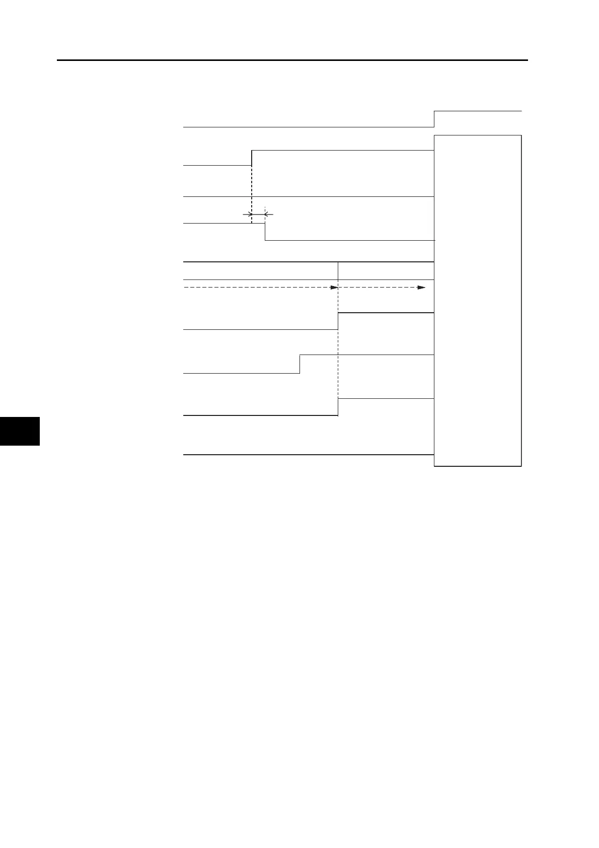
Timing of Return from Safety Status
*1. Make sure that servo ON input is turned OFF when you return the input signals of safety inputs 1 and
2 to ON. If an error exists in this state, be sure to clear the error when both safety inputs 1 and 2 have
returned to ON state. An error will occur immediately if the error reset is executed when even one of
them is still in OFF status.
*2. An error exists in this state. The dynamic brake operates according to the Fault reaction option code
(605E hex).
*3. An error exists in this state. The dynamic brake operates according to the Disable operation option
code (605C hex).
STO status
Normal status
Servo ON
Servo OFF command
No power supply
6 ms max.
READY
Error
Brake held
Reset
Normal
DB released/engaged
*2
Servo OFF
DB released/engaged
*3
Error
Safety input 1
Safety input 2
Servo ON /OFF
*1
Brake interlock
output (BKIR)
Motor power
is supplied.
Servo ready
completed output
(READY)
Error Output
(/ALM)
Error reset
input (RESET)
*1
Dynamic
brake relay
EDM output
ON
OFF
After the servo
turns ON, operation
will follow the
normal servo
ON/OFF operation
timing diagram.
For details, refer to
7-5 Brake Interlock.

 Loading...


