9-26
9-5 Interface Monitor Settings
OMNUC G5-series AC Servomotors and Servo Drives User’s Manual (with Built-in EtherCAT Communications)
9
Details on Servo Parameter Objects
Analog signals of various monitor values can be output from the analog monitor connector on the front
panel.
The monitor type to output and the scaling (or output gain) can be selected. These can be set for
each object.
Refer to 11-1 Analog Monitor on page 11-1.
Explanation of Set Values
Set the output gain for analog monitor 1.
Refer to 11-1 Analog Monitor on page 11-1.
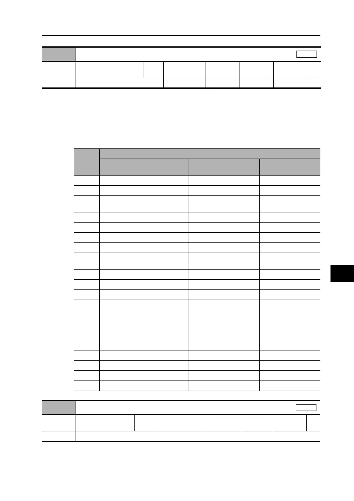
3416 hex
Analog Monitor 1 Selection
Setting
range
0 to 21 Unit −
Default
setting
0
Data
attribute
A
Size 2 bytes (INT16) Access RW PDO map Not possible.
All
Set
value
Explanation
Monitor type Unit
Output gain when
object 3417 hex = 0
0 Feedback Motor Speed r/min 500
1 Internal Command Motor Speed r/min 500
2
Filtered Internal Command Motor
Speed
r/min
500
3 Motor Control Effort r/min 500
4 Torque demand % (rated torque ratio) 33
5 Position Error pulses (command units) 3000
6 Pulse Position Error pulses (encoder units) 3000
7
Fully-closed error pulses (external encoder
units)
3000
8 Hybrid error pulses (command units) 3000
9 P-N voltage V 80
10 Regeneration load ratio % 33
11 Motor load ratio % 33
12 Forward External Torque Limit % (rated torque ratio) 33
13 Reverse External Torque Limit % (rated torque ratio) 33
14 Speed limit value r/min 500
15 Inertia ratio % 500
16 to 18 Reserved −−
19 Encoder temperature °C10
20 Servo Drive temperature °C10
21 Encoder 1-rotation data pulses (encoder units) 110000
3417 hex
Analog Monitor 1 Scale Setting
Setting
range
0 to 214,748,364 Unit
3416h monitor unit/
V
Default
setting
0
Data
attribute
A
Size 4 bytes (INT32) Access RW PDO map Not possible.
All

 Loading...


