2-32
2-4 External and Mounting Dimensions
OMNUC G5-series AC Servomotors and Servo Drives User’s Manual (with Built-in EtherCAT Communications)
2
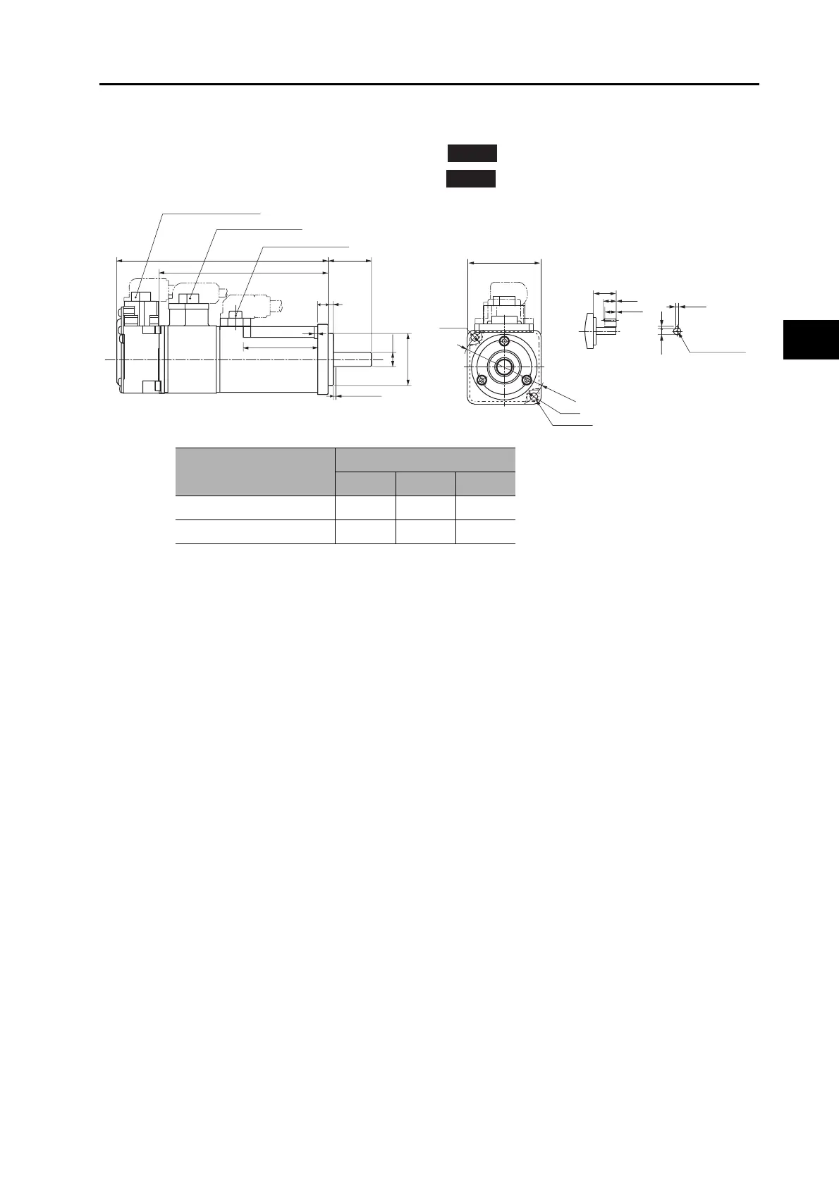
Models and External Dimensions
50 W/100 W (with Brake)
R88M-K05030H-B (S2)/-K10030@-B (S2)
R88M-K05030T-B (S2)/-K10030@-B (S2)
Note: The standard models have a straight shaft. Models with a key and tap are indicated with S2 at the
end of the model number.
INC
ABS
M3 (depth 6)
25
14
12.5
3h9
3
6.2
R3.7
R4.2
2-φ4.3
φ46±0.2
40×40
LL
LM
Motor connector
φ
8h6
φ30h7
25
36
2
1.5 min.
LN
(Shaft end specifications with key and tap)
Brake connector
Encoder connector
Model
Dimensions (mm)
LL LM LN
R88M-K05030@-B@ 102 78 23
R88M-K10030@-B@ 122 98 43

 Loading...


