4-19
4 System Design
G5 Series AC Servo Drives With Built-in EtherCAT Communications, Linear Motor Type
4-2 Wiring
4
4-2-2 Main Circuit and Linear Motor Connections
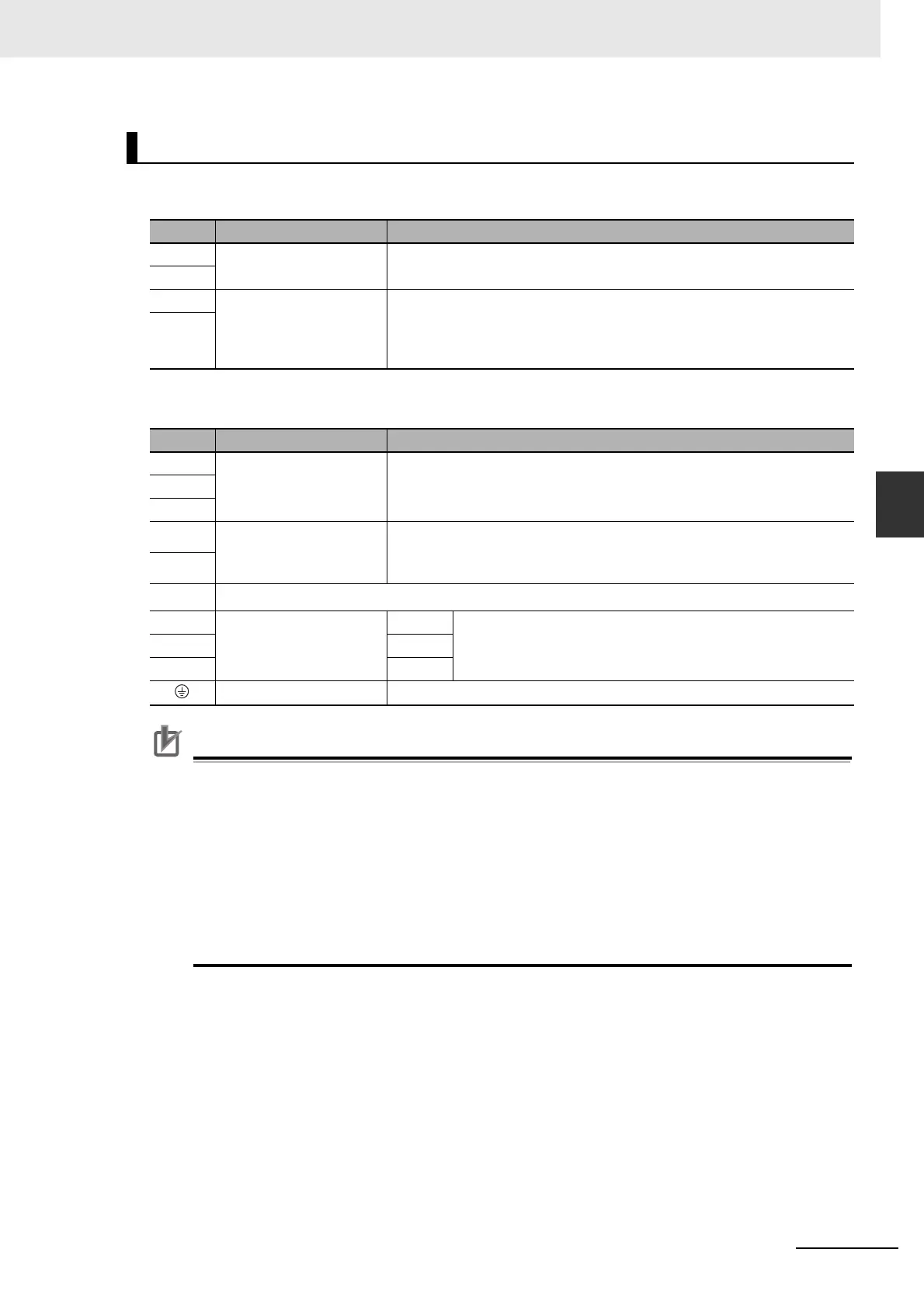
Terminal Block Specifications, Top Terminal Block (TB1)
Terminal Block Specifications, Bottom Terminal Block (TB2)
Precautions for Correct UsePrecautions for Correct Use
• Tighten the frame ground screw to a torque of 2.4 to 2.6 N·m (M6).
• Tighten the top terminal block screws to a torque of 0.7 to 1.0 N·m (M4). Exceeding the
maximum allowable torque for terminal block screws may cause damage to the terminal block.
• Tighten the bottom terminal block screws to a torque of 2.2 to 2.5 N·m (M6). Exceeding the
maximum allowable torque for terminal block screws may cause damage to the terminal block.
• Tighten the fixing screw of the terminal block cover to a torque of 2.0 to 2.5 N·m (M5).
• If you are connecting an External Regeneration Resistor, set the Regeneration Resistor
Selection servo parameter object (3016 hex).
• Do not connect any External Regeneration Resistors between B1 and NC.
R88D-KN150H-ECT-L
Symbol Name Function
L1C Control circuit power
supply input
Single-phase 200 to 230 VAC (170 to 253 VAC) 50/60 Hz
L2C
DB1 Dynamic Brake Resistor
control terminals
These terminals are used to control the MC for externally connected
dynamic brake resistance. The output contact specifications are 1 A max.
at 300 VAC/100 VDC max.
Connect them if required.
DB2
Symbol Name Function
L1 Main circuit power supply
input
3-phase 200 to 230 VAC (170 to 253 VAC) 50/60 Hz
L2
L3
B1 External Regeneration
Resistor connection
terminals
Connect an External Regeneration Resistor between B1 and B2.
B2
NC
Do not connect.
U Motor connection
terminals
Phase U These are the output terminals to the Linear Motor.
Be sure to wire them correctly.
V Phase V
W
Phase W
Frame ground This is the ground terminal. Ground to 100 or less.

 Loading...

