4 System Design
4-28
G5 Series AC Servo Drives With Built-in EtherCAT Communications, Linear Motor Type
*1 Use the same wire sizes for B1 and B2.
Wire Sizes and Allowable Current
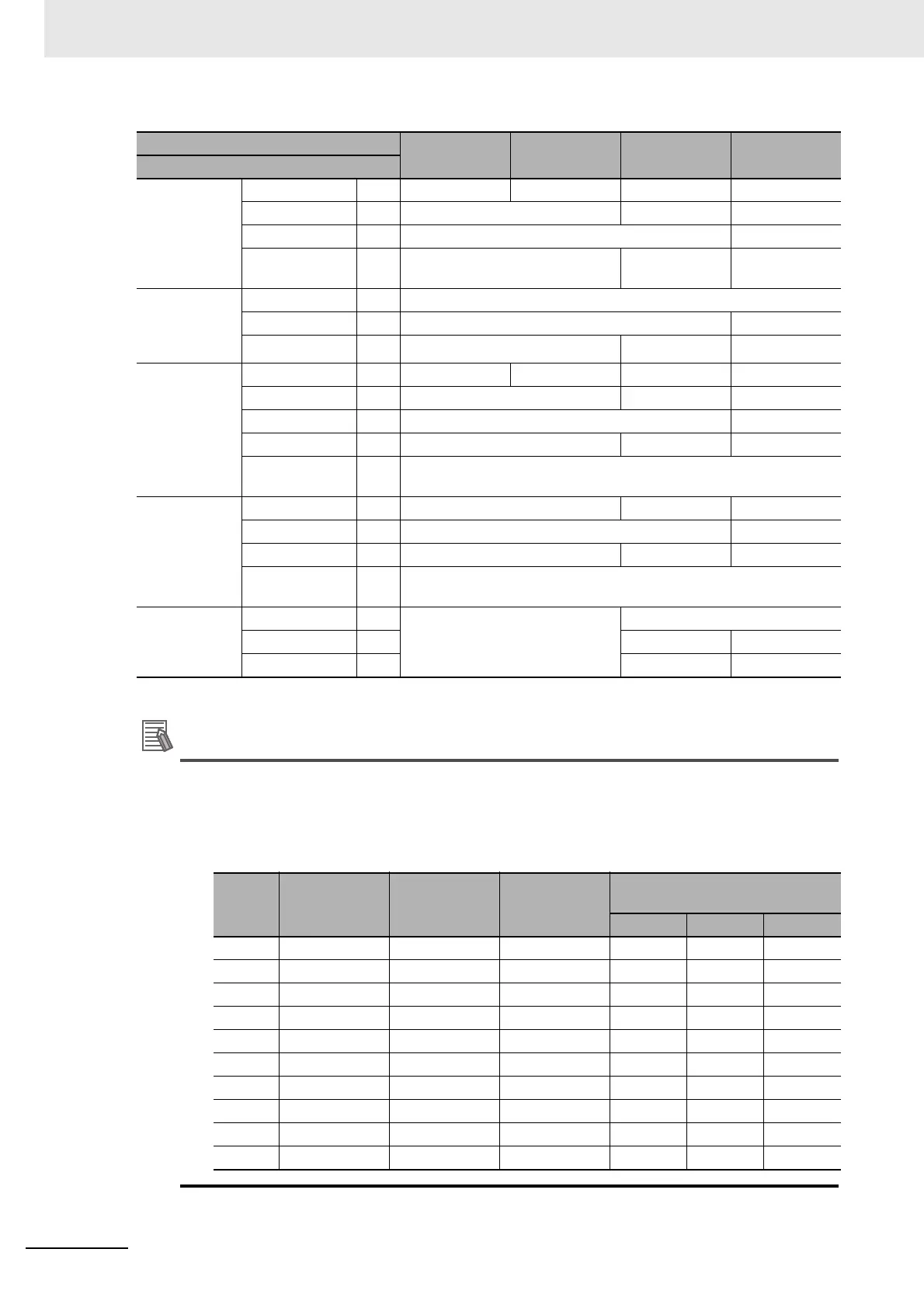
The following table shows the allowable current when there are 3 power supply wires. Use a
current below these specified values.
600-V Heat-resistant Vinyl Wire (HIV)
Model (R88D-)
KN30F-ECT-L KN50F-ECT-L KN75F-ECT-L
KN150F-ECT-L
Item Unit
Main circuit
power supply
input (L1 and
L3, or L1, L2
and L3)
Rated current A 7.6 12.1 16.0 29.0
Wire size AWG12
AWG10
AWG6
Screw size M5 M6
Tightening
torque
N·m 2.0
2.0 to 2.4 2.2 to 2.5
Control circuit
power supply
input (L1C and
L2C)
Wire size AWG18
Screw size M5 M4
Tightening torque
N·m 2.0
1.3 to 1.5 0.7 to 0.8
Motor
connection
terminals
(U, V, W, and
FG)
*1
Rated current A 9.4 16.5 22.0 33.4
Wire size AWG12 AWG6 AWG4
Screw size M5 M6
Tightening torque
N·m 2.0
2.0 to 2.4 2.2 to 2.5
Maximum wiring
length
m20
Frame ground
(FG)
Wire size AWG12 AWG6 AWG4
Screw size M5 M6
Tightening torque
N·m 2.0
1.4 to 1.6 2.4 to 2.8
Maximum wiring
length
m1
Dynamic brake
resister control
terminals
Wire size AWG18
Screw size M5 M6
Tightening torque
N·m
1.3 to 1.5 0.7 to 0.8
AWG
size
Nominal cross-
sectional area
[mm
2
]
Configuration
[wires/mm
2
]
Conductive
resistance
[/km]
Allowable current [A] for ambient
temperature
30C 40C 50C
20 0.5 19/0.18 39.5 6.6 5.6 4.5
0.75 30/0.18 26.0 8.8 7.0 5.5
18 0.9 37/0.18 24.4 9.0 7.7 6.0
16 1.25 50/0.18 15.6 12.0 11.0 8.5
14 2.0 7/0.6 9.53 23 20 16
12 3.5 7/0.8 5.41 33 29 24
10 5.5 7/1.0 3.47 43 38 31
8 8.0 7/1.2 2.41 55 49 40
6 14.0 7/1.6 1.35 79 70 57
4 22.0 7/2.0 0.85 99 88 70

 Loading...

