9 Servo Parameter Objects
9-26
G5 Series AC Servo Drives With Built-in EtherCAT Communications, Linear Motor Type
• Use this object to change the count direction of the external encoder.
Explanation of Settings
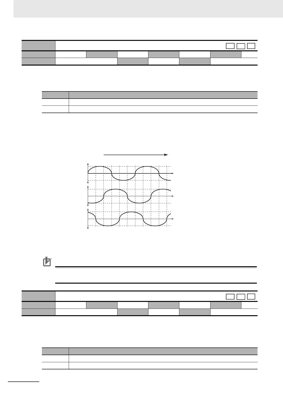
• Set the pulse count direction so that relationship between the count direction of the external encoder
and the induced voltage of the motor in each phase is as shown below.
• To check the external encoder count direction, disconnect the motor cable and monitor the Position
actual value (6064 hex) while manually operating the Motor Coil Unit.
*1 The waveform of the induced voltage monitored at the U terminal, with the W terminal connected to GND.
*2 The waveform of the induced voltage monitored at the V terminal, with the U terminal connected to GND.
*3 The waveform of the induced voltage monitored at the W terminal, with the V terminal connected to GND.
Precautions for Correct UsePrecautions for Correct Use
Before checking the count direction, be sure to set the Movement Direction Setting (3000 hex) to
1, write the setting to the EEPROM, and turn OFF and then ON the power supply.
• Set to enable or disable phase-Z disconnection detection when an external encoder with a 90 phase
difference output is used.
Explanation of Settings
3326 hex
External Feedback Pulse Direction Switching
Setting range 0 to 1 Unit
Default setting
0
Data attribute
R
Size 2 bytes (INT16) Access RW PDO map Not possible.
Set value Description
0 External feedback pulse direction not reversed
1 External feedback pulse direction reversed
3327 hex
External Feedback Pulse Phase-Z Setting
Setting range 0 to 1 Unit
Default setting
0
Data attribute
R
Size 2 bytes (INT16) Access RW PDO map Not possible.
Set value Description
0 Phase-Z disconnection detection enabled
1 Phase-Z disconnection detection disabled
0° 180° 360°
0
0
0
V
V
V
U - W (G)
*1
V - U (G)
*2
W - V (G)
*3
External encoder
count-down direction
Electric angle
Motor induced voltage

 Loading...

