5-1
5-1 Position Control
5
Operating Functions
5Operating Functions
5-1 Position Control
Positioning can be performed according to the pulses input into the pulse-string inputs (CN1-22 to
25).
The Servomotor rotates using the value of the pulse-string inputs multiplied by the value of the
electronic gear (Pn46, Pn47, Pn4A, and Pn4B).
SMARTSTEP2 Series Servo Drives have two position control modes: high-response position
control and advanced position control. Select the mode better suited for your operational
conditions.
High-Response Position Control vs. Advanced Position Control
The two position control modes have the following differences.
The Notch Filter 1 Frequency, Vibration Frequency, and Realtime Autotuning Mode Selection
cannot be used at the same time in high-response position control mode. The parameter entered
first will be given priority.
Example: When the Realtime Autotuning Mode Selection is set, the Servo Drive will be forcibly set
to 1500 (disabled), even if the Notch Filter 1 Frequency is input.
The adaptive filter will be disabled under high-response position control. To use the adaptive filter,
select the advanced position control mode.
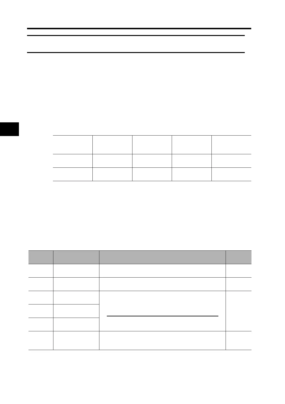
Parameters Requiring Settings
Notch Filter 1
Frequency (Pn1D)
Vibration
Frequency (Pn2B)
Realtime Autotun-
ing Mode Selec-
tion (Pn21)
Adaptive Filter
Table Number
Display (Pn2F)
High-Response
Position Control
Conditional Conditional Conditional Disabled
Advanced
Position Control
Enabled Enabled Enabled Enabled
Parameter
No.
Parameter name Explanation Reference
Pn02
Control Mode
Selection
Select a control mode for position control (setting: 0 or 2).
Page 5-33
Pn42
Command Pulse
Mode
Set to match the command pulse form of the controller.
Page 5-49
Pn46
Electronic Gear Ratio
Numerator 1
Set the pulse rate for command pulses and Servomotor travel
amount.
The maximum value of the calculated numerator is 2,621,440.
Page 5-50Pn4A
Electronic Gear Ratio
Numerator Exponent
Pn4B
Electronic Gear Ratio
Denominator
Pn60
Positioning
Completion Range
The Positioning Completed Output (INP) turns ON when the
number of pulses in the deviation counter is equal to or less than
the setting of this parameter.
Page 5-55
Electronic Gear Ratio Numerator 1 (Pn46) x 2
Electronic Gear Ratio Numerator Exponent (Pn4A)
Electronic Gear Ratio Denominator
Pn4B

 Loading...


