7-10
7-3 Autotuning
7
Adjustment Functions
both forward and reverse for approximately 15 seconds. This will be repeated up to 5 cycles. It is
not an error if the Servomotor stops before cycling 5 times.
Repeat step 4 (Selecting Machine Rigidity) to step 7 (Executing Autotuning) until satisfactory
responsiveness can be obtained.
8. Saving the Gain Settings
When system responsiveness is satisfactory, move to Parameter Write Mode and save the
settings in EEPROM so they will not be lost. (For details on operations, refer to Parameter Write
Mode on page 6-15.)
To save the new settings, move to Parameter Write Mode and save the parameters in EEPROM.
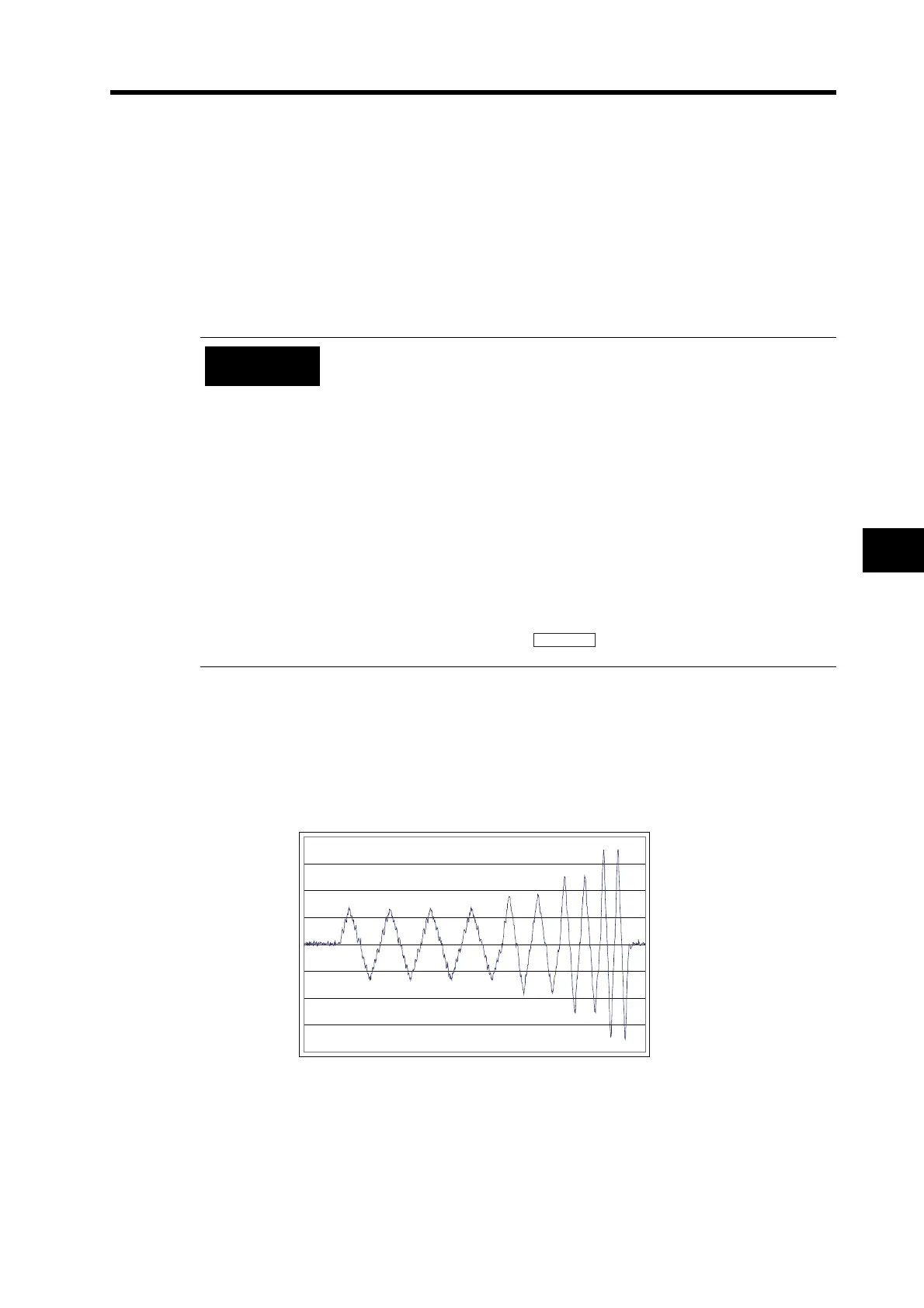
Autotuning Operation Waveform
The following figure illustrates how the operation waveform will appear when autotuning is
executed. The waveform will be distorted immediately after the execution, but will gradually smooth
out.
Execute autotuning when a load is connected. If autotuning is executed
without a load (i.e., Servomotor/Servo Drive only) the Inertia Ratio (Pn20)
will be 0.
A tuning error will occur if any of the following conditions occur while
autotuning is being executed.
(1) If an error occurs. If the Servo is turned OFF, e.g., the RUN Command
Input (RUN) is turned OFF. If the deviation counter is reset, e.g., using
the Deviation Counter Reset Input (ECRST). If auto tuning is executed
near a limit sensor.
(2) If the inertia or load is too large and the output torque becomes
saturated.
(3) If oscillation occurs and tuning cannot be performed correctly.
If a tuning error occurs, the setting of each gain parameter will return to the
value before tuning was executed. Except for times when an error occurs,
the Servomotor will not stop.
Depending on the load,
the message does not appear and
oscillation may occur.
Precautions
for Correct Use

 Loading...


