2-22
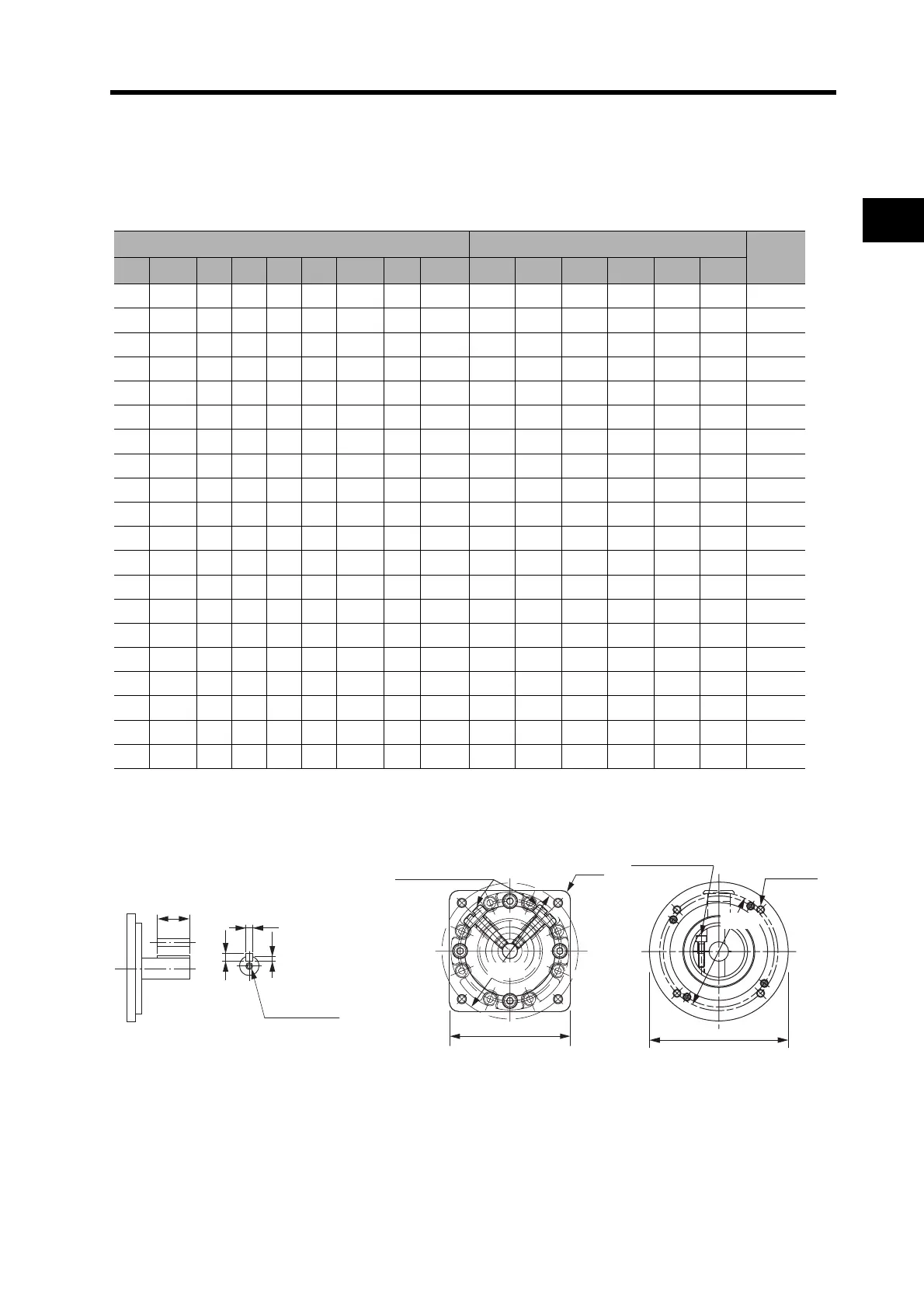
2-2 External and Mounted Dimensions
2
Standard Models and Dimensions
*1. This is the set bolt.
Dimensions (mm) Key and tap dimensions (mm)
Weight
(kg)
E F1 F2 G S T Z1 Z2 AT
*1
QK b h t1 M L
27 2.2 15 5 8 20 3.4 M4 M3
15 3 3 1.8 M3 6 0.29
27 2.2 15 5 8 20 3.4 M4 M3
15 3 3 1.8 M3 6 0.29
37 2.5 21 8 16 28 5.5 M4 M3
25553M4 81.04
37 2.5 21 8 16 28 5.5 M4 M3
25553M4 81.04
37 2.5 21 8 16 28 5.5 M4 M3
25553M4 81.04
27 2.2 15 5 8 20 3.4 M4 M3
15 3 3 1.8 M3 6 0.29
37 2.5 21 8 16 28 5.5 M4 M3
25553M4 81.04
37 2.5 21 8 16 28 5.5 M4 M3
25553M4 81.04
53 7.5 27 10 25 42 9.0 M4 M4
36874.0M612 2.4
53 7.5 27 10 25 42 9.0 M4 M4
36874.0M612 2.4
37 2.5 21 8 16 28 5.5 M4 M3
25553M4 81.02
37 2.5 21 8 16 28 5.5 M4 M3
25553M4 81.09
53 7.5 27 10 25 42 9.0 M4 M4
36874.0M612 2.9
53 7.5 27 10 25 42 9.0 M4 M4
36874.0M612 2.9
53 7.5 27 10 25 42 9.0 M4 M4
36874.0M612 2.9
37 2.5 21 8 16 28 5.5 M4 M3
25553M4 81.09
53 7.5 27 10 25 42 9.0 M4 M4
36874.0M612 2.9
53 7.5 27 10 25 42 9.0 M4 M4
36874.0M612 2.9
98 12.5 35 13 40 82 11.0 M4 M4
70 12 8 5.0 M10 20 7.5
98 12.5 35 13 40 82 11.0 M4 M4
70 12 8 5.0 M10 20 7.5
For the R88G-HPG11B Series, two set bolts
are positioned at 90° from each other.
Set bolts (AT)
4-Z2
C2 × C2
D2 dia.
C2 dia.
Four, Z2
Set bolt (AT)
D2 dia.
QK
Key and Tap Dimensions
b
h
t1
M (depth: L)
 Loading...


