Chapter 2
2-23
Standard Models and Specifications
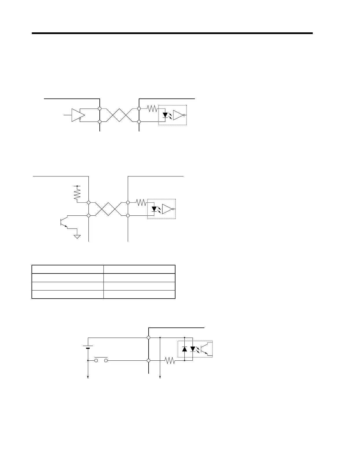
■ Control Input Circuits
● Position Command Pulse Inputs and Deviation Counter Reset Inputs
Line Driver Input
Open Collector Input
Using External Power Supply
Note Select a value for resistance R so that the input current will be from 7 to 15 mA.
● Sequence Inputs
Signal Levels ON level: Minimum (+24VIN-11) V
OFF level: Maximum (+24VIN-1) V
Vcc R
24 V 1.6 to 2.4 k
Ω
12 V 750 to 1.1 kΩ
5 V None
Controller
Servo Driver
Applicable line driver:
AM26LS31A or equivalent
Input current: 7 mA, 3 V
200 Ω
+
−
+
−
Controller
Servo Driver
Input current: 7 to 15 mA
200 Ω
+
−
Vcc
R
External power supply:
24 V + 1 V DC
Power supply capacity:
50 mA min. (per Unit)
To other input circuit GNDs
To other input circuits
Photocoupler input: 24 V DC, 7 mA
Servo Driver
13+24VIN
14
3.3 k
Minimum ON time: 2 ms