Chapter 2
2-49
Standard Models and Specifications
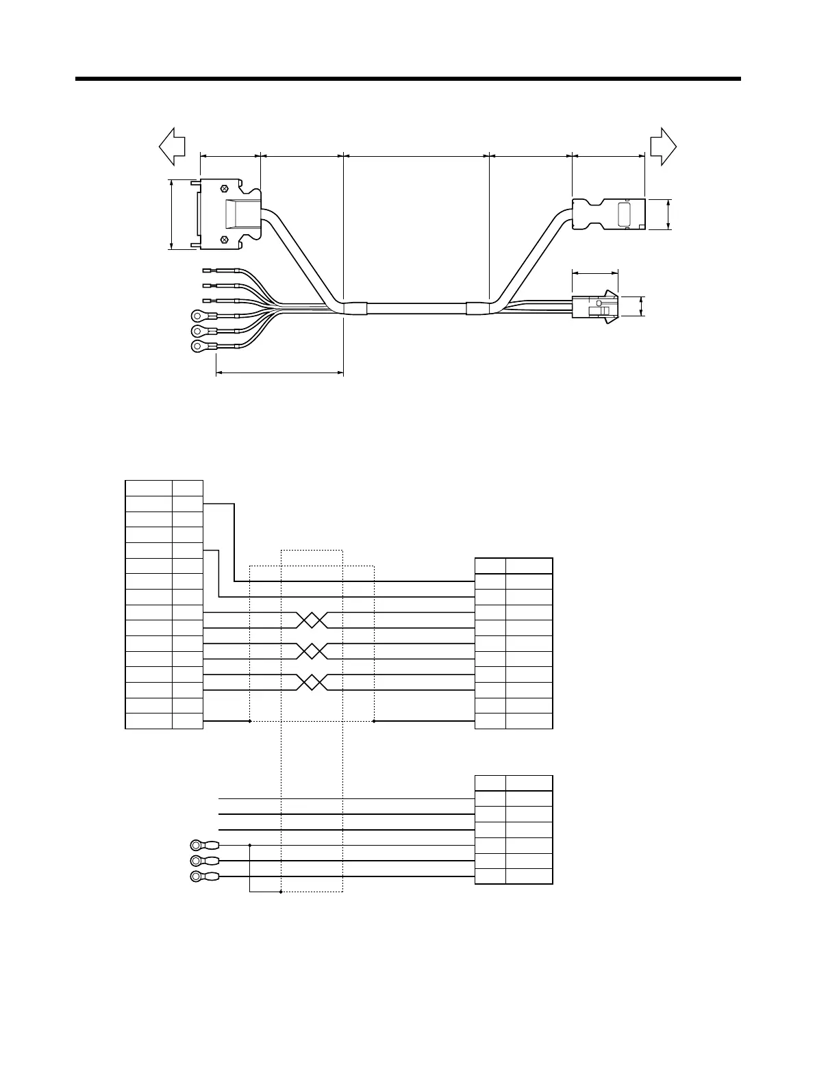
● Connection Configuration and External Dimensions
● Wiring
Servo Driver
Servomotor
R7D-AP@
R7M-A@
5039 50L
80
t=28.4
14
27.4
t=12
43.7
21.5
t=12.7
29.5
Symbol No.
Servo Driver
E0V 1
E0V 2
E0V 3
E5V 4
E5V 5
E5V 6
− 7
S+ 8
S− 9
A+ 10
A− 11
B+ 12
B− 13
− 14
FG Shell
SymbolNo.
Servomotor
7 E0V
8 E5V
5
6
1
2
3
4
S+
S−
A+
A−
B+
B−
Shell FG
AWG22 Black
AWG22 Red
AWG24 Green
AWG24 Green/White
AWG24 Blue
AWG24 Blue/White
AWG24 Yellow
AWG24 Yellow/White
SymbolNo.
1 U phase
2 V phase
3
4
W phase
FG
5 Brake
6 Brake
AWG20 Red
AWG20 White
AWG20 Blue
AWG20 Green/Yellow
M4 crimp terminal
AWG20 Black
M4 crimp terminal
AWG20 Brown
M4 crimp terminal
Connector kit:
54280-0800 (Molex Japan)
Connector cap:
350781-1 (Tyco Electronics AMP)
Connector socket
350570-3 (Tyco Electronics AMP)
Connector plug:
10114-3000VE (Sumitomo 3M)
Connector case:
10314-52A0-008 (Sumitomo 3M)