242
Cycle Time/High-speed Processing Section 6-1
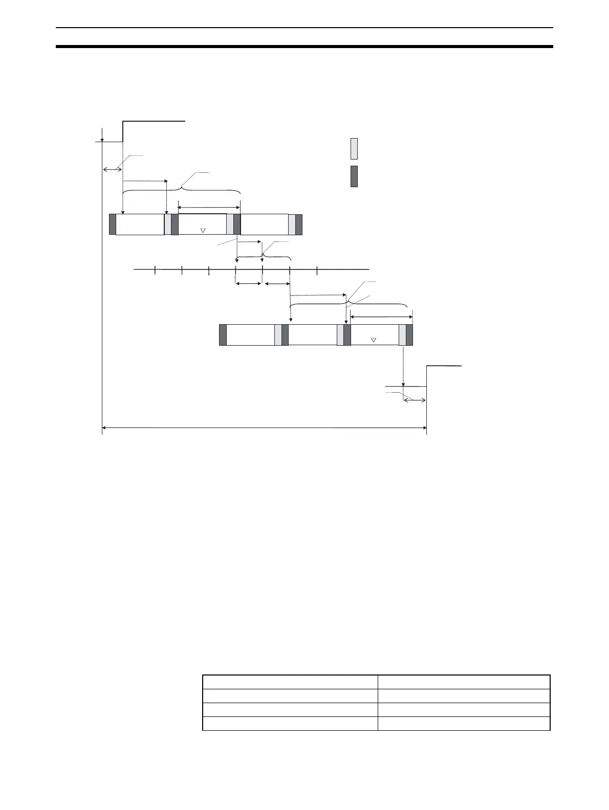
6-1-9 Maximum Data Link I/O Response Time
Normal Processing The following diagram illustrates the data flow that will produce the maximum
data link I/O response time when DLNK(226) is not used.
There are three points shown in the diagram above where processing is
delayed, increasing the data link I/O response time.
1,2,3... 1. The input arrives in the PLC (CPU Unit #1) just after I/O refreshing, caus-
ing a delay of one cycle before the input is read into the PLC. CPU Bus
Units are refreshed after program execution, causing a total delay of two
cycle times.
2. Data exchange occurs just after the PLC passes the token that makes it
the polling node, causing a delay of up to one communications cycle time
before the data is transferred in data link processing. There will also be a
delay of up to one communications cycle time after receiving the token,
causing a total delay of up to two communications cycle times.
3. The data transferred in data link processing arrives at the PLC (CPU Unit
#2) after data exchange, so the data will not be read into the PLC until the
next data exchange, causing a delay of up to one cycle. CPU Bus Units
are refreshed after program execution, causing a total delay of two cycle
times.
The equation for maximum data link I/O response time is as follows:
×
×
×
Input Unit
Input
Input ON delay
(1) Delay of two cycle times
Basic I/O Units
refreshed.
CPU Bus Units refreshed
(including data links)
One cycle time
Data transfer to
Controller Link Unit
Processing in
CPU Unit #1
(2) Delay of two communications cycle times
One com-
munica-
tions cycle
Data link transmissions
(3) Delay of two cycle times
Data received from Controller Link Unit
One cycle time
Output Unit
Output ON delay
Processing in
CPU Unit #2
Maximum data link I/O response time
Program
execution
Program
execution
Input ON delay 1.5 ms
Cycle time of PLC at CPU Unit #1 × 225 ms × 2
Communications cycle time × 210 ms × 2
Cycle time of PLC at CPU Unit #2 × 220 ms × 2