16
Rotary Switch Settings
The Host Link Unit provides rotary switches on the front panel used to set the
Host Link Unit’s unit number and node number for identification in the Host Link
System. Set the rotary switches only when the PC is turned off.
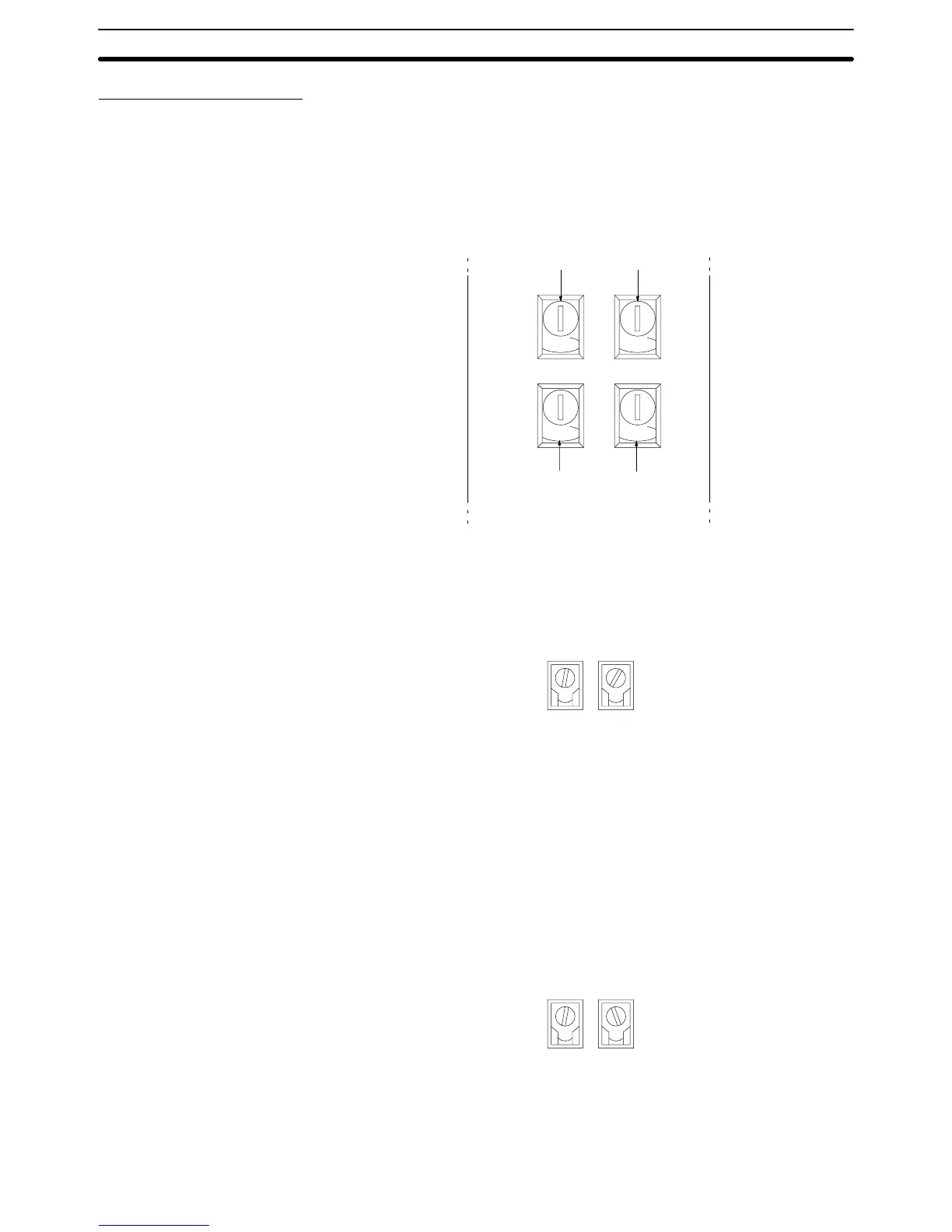
Location of Rotary Switches The rotary switches are located beneath the indicators and appear as shown in
the following illustration. SW1 and SW2 are used to set the Host Link Unit’s unit
number as a CPU Bus Unit; SW3 and SW4 are used to set the node number for
the Host Link Unit’s communications port 2.
0
NODE
No.
X10
1
0
0
UNIT
No.
X10
1
0
SW1 SW2
SW3 SW4
X10
0
X10
0
Set the unit number to a unique number between 0 and 15 in the decimal. This is
the unit number of the Host Link Unit as a CPU Bus Unit. Do not use the same
number on two CPU Bus Units in the same PC.
Set the 10’s digit of the unit number with SW1 and the 1’s digit with SW2. In the
following example, the unit number is set to 12.
1
UNIT
No.
X10
1
SW1
2
X10
0
SW2
Note 1. The node number must not be larger than 15. If a node number larger than
15 is set, an error will result and the ERH indicator on the display panel will
light.
2. Each CPU Bus Unit for a PC must have a unique unit number.
If more than one PC is connected to a host computer (e.g., one via the CPU’s
host interface and one via the Host Link Unit), each link is identified by a node
number. The node number of port 2 is set here. The node number of communica-
tions port 1 is fixed to 00.
Set a node number between 0 and 31 in decimal. Set the 10’s digit of a node
number with SW3 and the 1’s digit with SW4. In the following example, the node
number of the Host Link Unit is set to 29.
2
NODE
No.
X10
1
SW3
9
X10
0
SW4
Note 1. The node number must not be larger than 31. If a node number larger than
31 is set, an error will result and the ERC2 indicator on the display panel will
light.
Unit Number (SW1 and
SW2)
Node Number of
Communications Port 2
(SW3 and SW4)
Host Link Unit Settings and Parameters Section 2-2